Cirkit Designer Logo
Cirkit Designer
Your all-in-one circuit design IDE
Home / 
Component Documentation

How to Use MPU 6050: Examples, Pinouts, and Specs

Image of MPU 6050
Cirkit Designer LogoDesign with MPU 6050 in Cirkit Designer

Introduction

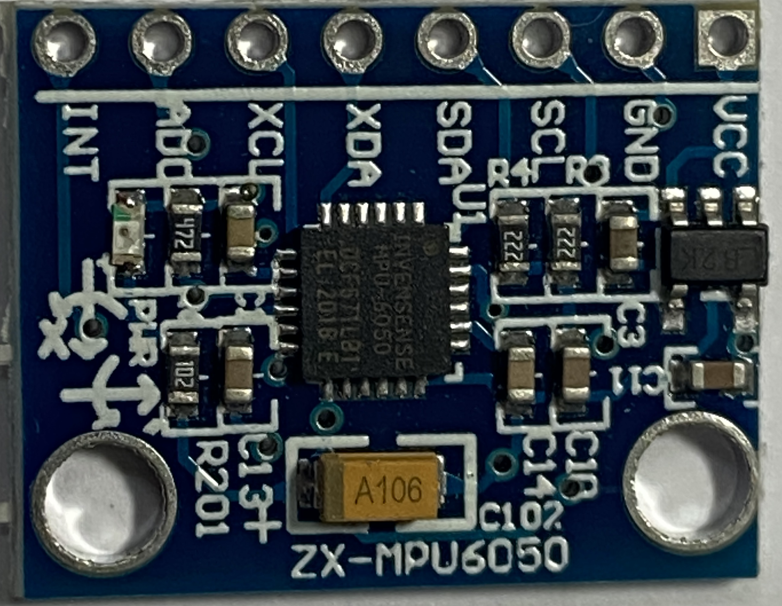
The MPU 6050 is a 6-axis motion tracking device that combines a 3-axis gyroscope and a 3-axis accelerometer. This versatile sensor is widely used in applications requiring motion sensing and orientation detection, such as:

  • Drones and UAVs
  • Robotics
  • Gaming controllers
  • Wearable devices
  • Smartphones and tablets
  • Motion capture systems

Explore Projects Built with MPU 6050

Use Cirkit Designer to design, explore, and prototype these projects online. Some projects support real-time simulation. Click "Open Project" to start designing instantly!
ESP32-Controlled Multi-MPU6050 and MPU9250 IMU Data Aggregator
Image of gant vr: A project utilizing MPU 6050 in a practical application
This circuit features an ESP32 microcontroller interfaced with multiple MPU-6050 sensors and a single MPU-9250 sensor through an Adafruit TCA9548A I2C multiplexer, allowing for the reading of multiple inertial measurement units (IMUs) over the same I2C bus. The ESP32 collects and processes acceleration and gyroscopic data from the sensors to calculate angles in the X and Y axes. Power management is handled by a TP4056 charging module and an AMS1117 voltage regulator, which together with two 18650 Li-ion batteries, provide a stable power supply for the microcontroller and sensors.
Cirkit Designer LogoOpen Project in Cirkit Designer
Arduino UNO and MPU-6050 Based Motion Sensing System
Image of mi: A project utilizing MPU 6050 in a practical application
This circuit uses an Arduino UNO to interface with an MPU-6050 accelerometer and gyroscope sensor. The Arduino reads motion data from the MPU-6050 via I2C communication and outputs the processed data to the serial monitor.
Cirkit Designer LogoOpen Project in Cirkit Designer
Arduino UNO and MPU-6050 Based Motion Sensing System with I2C Interface
Image of mpu6050new: A project utilizing MPU 6050 in a practical application
This circuit features an Arduino UNO connected to an MPU-6050 accelerometer and gyroscope sensor via an I2C module. The Arduino UNO provides power to the sensor and communicates with it using the I2C protocol, enabling the collection of motion and orientation data.
Cirkit Designer LogoOpen Project in Cirkit Designer
ESP32-Based Accident Detection and GPS Tracking System with GSM Notifications
Image of hello: A project utilizing MPU 6050 in a practical application
This circuit features an ESP32 microcontroller interfaced with an MPU6050 accelerometer/gyroscope, a Neo 6M GPS module, and a SIM800L GSM module. The ESP32 communicates with the MPU6050 via I2C (SCL and SDA lines) to detect potential accidents based on acceleration thresholds, with the GPS module providing location data via a serial connection (RX0 and TX0). The SIM800L GSM module is connected to the ESP32 through another serial interface (RX2 and TX2) to send SMS alerts with location information in case of an accident detection.
Cirkit Designer LogoOpen Project in Cirkit Designer

Explore Projects Built with MPU 6050

Use Cirkit Designer to design, explore, and prototype these projects online. Some projects support real-time simulation. Click "Open Project" to start designing instantly!
Image of gant vr: A project utilizing MPU 6050 in a practical application
ESP32-Controlled Multi-MPU6050 and MPU9250 IMU Data Aggregator
This circuit features an ESP32 microcontroller interfaced with multiple MPU-6050 sensors and a single MPU-9250 sensor through an Adafruit TCA9548A I2C multiplexer, allowing for the reading of multiple inertial measurement units (IMUs) over the same I2C bus. The ESP32 collects and processes acceleration and gyroscopic data from the sensors to calculate angles in the X and Y axes. Power management is handled by a TP4056 charging module and an AMS1117 voltage regulator, which together with two 18650 Li-ion batteries, provide a stable power supply for the microcontroller and sensors.
Cirkit Designer LogoOpen Project in Cirkit Designer
Image of mi: A project utilizing MPU 6050 in a practical application
Arduino UNO and MPU-6050 Based Motion Sensing System
This circuit uses an Arduino UNO to interface with an MPU-6050 accelerometer and gyroscope sensor. The Arduino reads motion data from the MPU-6050 via I2C communication and outputs the processed data to the serial monitor.
Cirkit Designer LogoOpen Project in Cirkit Designer
Image of mpu6050new: A project utilizing MPU 6050 in a practical application
Arduino UNO and MPU-6050 Based Motion Sensing System with I2C Interface
This circuit features an Arduino UNO connected to an MPU-6050 accelerometer and gyroscope sensor via an I2C module. The Arduino UNO provides power to the sensor and communicates with it using the I2C protocol, enabling the collection of motion and orientation data.
Cirkit Designer LogoOpen Project in Cirkit Designer
Image of hello: A project utilizing MPU 6050 in a practical application
ESP32-Based Accident Detection and GPS Tracking System with GSM Notifications
This circuit features an ESP32 microcontroller interfaced with an MPU6050 accelerometer/gyroscope, a Neo 6M GPS module, and a SIM800L GSM module. The ESP32 communicates with the MPU6050 via I2C (SCL and SDA lines) to detect potential accidents based on acceleration thresholds, with the GPS module providing location data via a serial connection (RX0 and TX0). The SIM800L GSM module is connected to the ESP32 through another serial interface (RX2 and TX2) to send SMS alerts with location information in case of an accident detection.
Cirkit Designer LogoOpen Project in Cirkit Designer

Technical Specifications

Key Technical Details

Parameter Value
Supply Voltage 2.3V - 3.4V
Operating Current 3.9mA
Gyroscope Range ±250, ±500, ±1000, ±2000 °/s
Accelerometer Range ±2g, ±4g, ±8g, ±16g
Communication I2C
I2C Address 0x68 (default), 0x69
Operating Temperature -40°C to +85°C

Pin Configuration and Descriptions

Pin Name Description
1 VCC Power supply (2.3V - 3.4V)
2 GND Ground
3 SCL I2C Clock
4 SDA I2C Data
5 XDA Auxiliary I2C Data (optional, not commonly used)
6 XCL Auxiliary I2C Clock (optional, not commonly used)
7 AD0 I2C Address Select (connect to GND for 0x68, VCC for 0x69)
8 INT Interrupt (optional, used for motion detection)
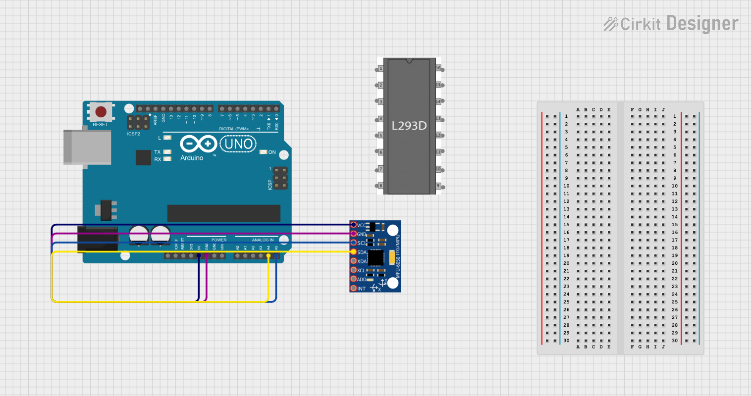
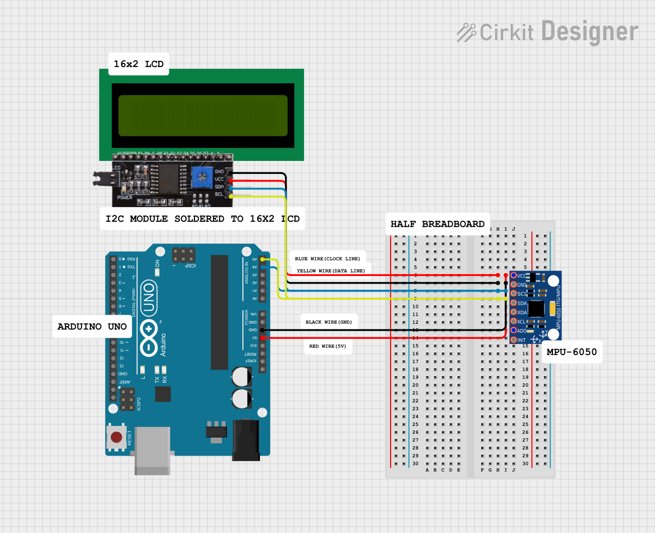
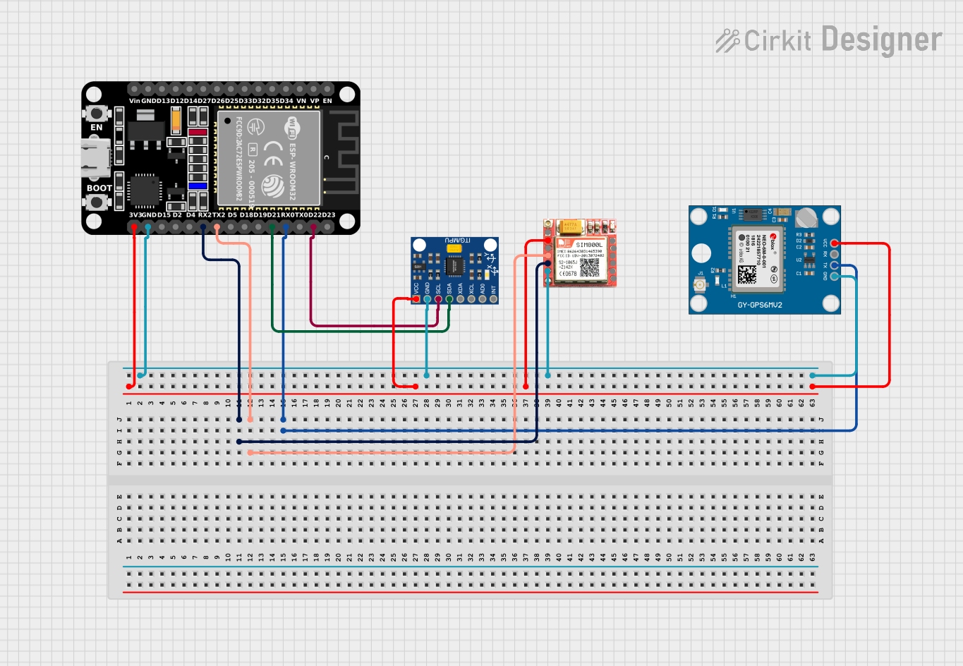
Usage Instructions

How to Use the MPU 6050 in a Circuit

  1. Power the Sensor: Connect the VCC pin to a 3.3V power supply and the GND pin to ground.
  2. I2C Communication: Connect the SCL pin to the I2C clock line and the SDA pin to the I2C data line of your microcontroller.
  3. Address Selection: Connect the AD0 pin to GND for the default I2C address (0x68) or to VCC for the alternate address (0x69).
  4. Optional Connections: If needed, connect the INT pin to a digital input on your microcontroller to use the interrupt feature.

Important Considerations and Best Practices

  • Voltage Levels: Ensure that the voltage levels of the I2C lines match the logic levels of your microcontroller. Use level shifters if necessary.
  • Bypass Capacitors: Place a 0.1µF capacitor close to the VCC pin to filter out noise.
  • Pull-up Resistors: Use 4.7kΩ pull-up resistors on the SCL and SDA lines if they are not already present on your microcontroller board.
  • Mounting: Secure the MPU 6050 on a stable platform to minimize vibrations and improve accuracy.

Example Code for Arduino UNO

#include <Wire.h>
#include <MPU6050.h>

MPU6050 mpu;

void setup() {
  Wire.begin();
  Serial.begin(9600);

  // Initialize MPU6050
  Serial.println("Initializing MPU6050...");
  if (!mpu.begin(MPU6050_SCALE_2000DPS, MPU6050_RANGE_2G)) {
    Serial.println("Could not find a valid MPU6050 sensor, check wiring!");
    while (1);
  }

  // Calibrate gyroscope. The calibration must be at rest.
  Serial.println("Calibrating gyroscope...");
  mpu.calibrateGyro();

  // Set threshold sensibility. Default 3.
  mpu.setThreshold(3);
}

void loop() {
  Vector rawAccel = mpu.readRawAccel();
  Vector normAccel = mpu.readNormalizeAccel();

  Serial.print(" Xraw = ");
  Serial.print(rawAccel.XAxis);
  Serial.print(" Yraw = ");
  Serial.print(rawAccel.YAxis);
  Serial.print(" Zraw = ");
  Serial.print(rawAccel.ZAxis);
  Serial.print(" Xnorm = ");
  Serial.print(normAccel.XAxis);
  Serial.print(" Ynorm = ");
  Serial.print(normAccel.YAxis);
  Serial.print(" Znorm = ");
  Serial.println(normAccel.ZAxis);

  delay(500);
}

Troubleshooting and FAQs

Common Issues

  1. No Communication with MPU 6050:

    • Solution: Check the I2C connections and ensure the correct I2C address is used. Verify that pull-up resistors are present on the SCL and SDA lines.
  2. Inaccurate Readings:

    • Solution: Ensure the sensor is mounted securely and away from sources of vibration. Calibrate the sensor before use.
  3. Sensor Not Detected:

    • Solution: Verify the power supply voltage and connections. Check for any loose wires or poor solder joints.

FAQs

Q: Can I use the MPU 6050 with a 5V microcontroller? A: Yes, but you will need to use level shifters for the I2C lines to match the 3.3V logic level of the MPU 6050.

Q: How do I change the I2C address of the MPU 6050? A: Connect the AD0 pin to GND for the default address (0x68) or to VCC for the alternate address (0x69).

Q: What is the maximum sampling rate of the MPU 6050? A: The MPU 6050 can sample data at a maximum rate of 1kHz.

Q: Can I use the MPU 6050 for tilt sensing? A: Yes, the accelerometer in the MPU 6050 can be used to measure tilt angles.

By following this documentation, you should be able to effectively integrate the MPU 6050 into your projects and troubleshoot common issues. Happy building!