How to Use 74LVC245 Octal 2-Way Tranceiver: Examples, Pinouts, and Specs
Introduction
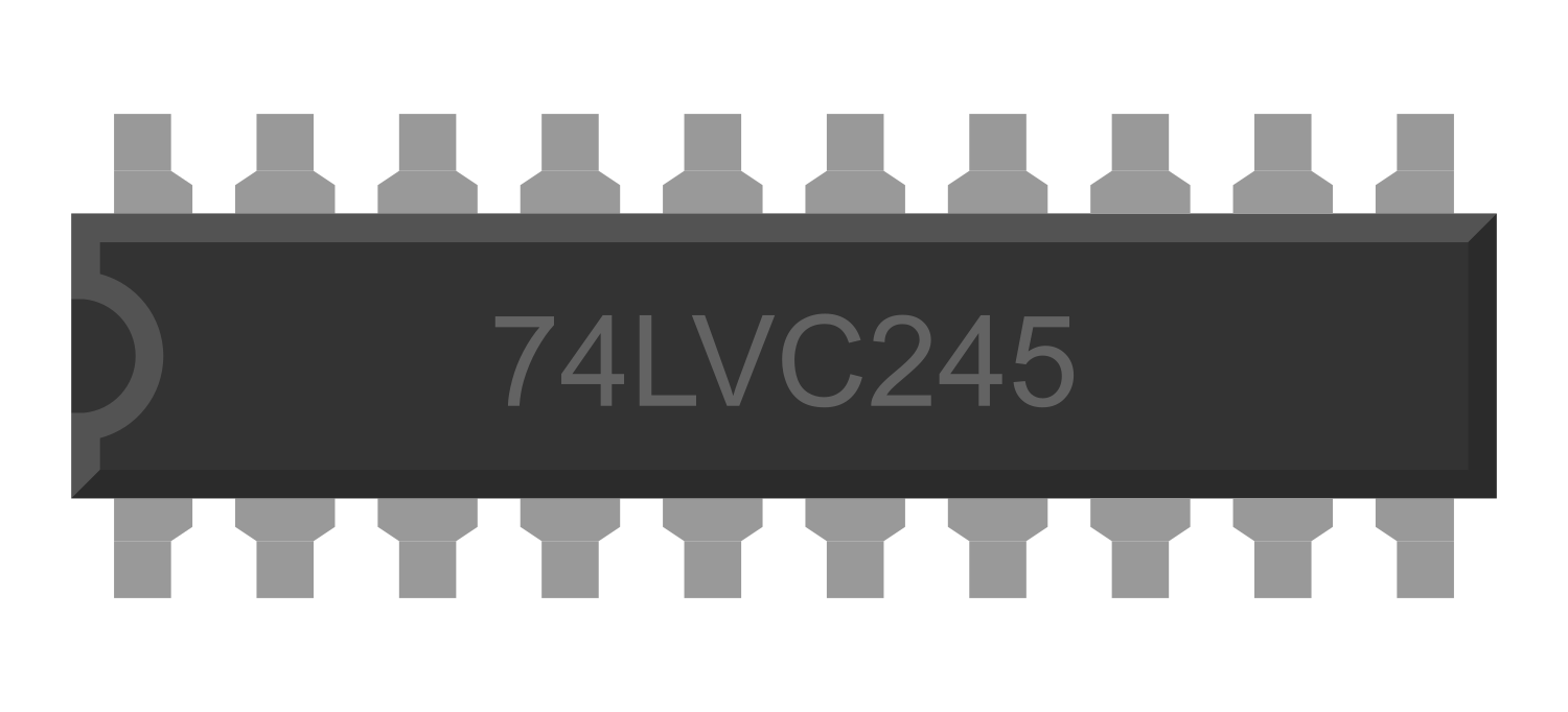
The 74LVC245 Octal 2-Way Transceiver is an integrated circuit designed to facilitate bidirectional level shifting and voltage translation between two independent buses. It is particularly useful in digital circuits where communication between devices operating at different voltage levels is required. The 74LVC245 is capable of transferring data from the A bus to the B bus and vice versa, depending on the logic level at the direction control (DIR) input. It is widely used in microcontroller interfacing, data communication, and other applications that require voltage level translation.
Explore Projects Built with 74LVC245 Octal 2-Way Tranceiver
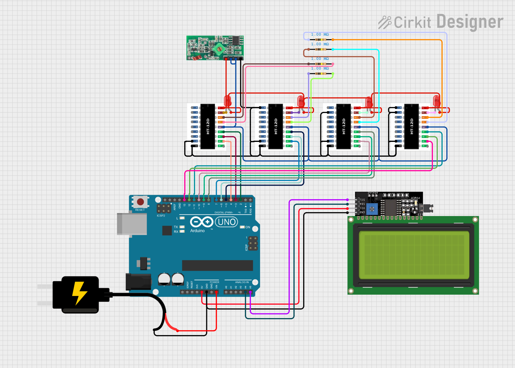


Explore Projects Built with 74LVC245 Octal 2-Way Tranceiver
Technical Specifications
Key Technical Details
- Supply Voltage (Vcc): 1.65V to 5.5V
- Input Voltage (Vi): -0.5V to 7.0V
- Output Voltage (Vo): -0.5V to Vcc + 0.5V
- Output Current (Io): ±24 mA
- Operating Temperature Range: -40°C to +85°C
Pin Configuration and Descriptions
| Pin Number | Name | Description |
|---|---|---|
| 1 | OE | Output Enable (Active Low) |
| 2-9 | A1-A8 | Side A Inputs/Outputs |
| 10 | GND | Ground |
| 11-18 | B1-B8 | Side B Inputs/Outputs |
| 19 | DIR | Direction Control |
| 20 | Vcc | Supply Voltage |
Usage Instructions
How to Use the Component in a Circuit
- Power Supply: Connect Vcc to a power supply within the range of 1.65V to 5.5V and GND to the system ground.
- Direction Control: Apply a logic high to the DIR pin to transfer data from A to B or a logic low to transfer data from B to A.
- Output Enable: To enable the outputs, connect the OE pin to a logic low level. To disable the outputs and place them in a high-impedance state, set OE to a logic high level.
- Data Transfer: Connect the data lines A1-A8 and B1-B8 to the respective buses for data transfer.
Important Considerations and Best Practices
- Ensure that the power supply voltage (Vcc) is within the specified range to prevent damage to the device.
- Avoid applying voltages to the input/output pins that exceed the supply voltage (Vcc) or fall below ground (GND).
- Use pull-up or pull-down resistors on the data lines if the connected devices do not have defined logic levels when inactive.
- Decouple the power supply with a 0.1 µF capacitor close to the Vcc pin to filter out noise.
Troubleshooting and FAQs
Common Issues
- Data not transferring correctly: Ensure that the DIR and OE pins are correctly configured. Check the voltage levels on both buses to ensure they are within acceptable ranges.
- Outputs not responding: Verify that the OE pin is not set high, as this will disable the outputs.
Solutions and Tips for Troubleshooting
- Double-check the pin connections and ensure that there are no short circuits.
- Measure the voltage levels on the Vcc and GND pins to ensure proper power supply.
- Use an oscilloscope to monitor the data lines for proper signal integrity.
FAQs
Q: Can the 74LVC245 be used to translate between 5V and 3.3V logic levels?
A: Yes, the 74LVC245 can be used for level shifting between 5V and 3.3V logic levels.
Q: What happens if the OE pin is left floating?
A: If the OE pin is left floating, the outputs may behave unpredictably. It is recommended to tie the OE pin to a known logic level.
Q: Is it necessary to connect all A and B pins if not all are used?
A: No, it is not necessary to connect all pins. Unused pins can be left unconnected or tied to a known logic level if desired.
Example Code for Arduino UNO
// Example code to demonstrate the use of the 74LVC245 with an Arduino UNO
// This example assumes the 74LVC245 is used for level shifting between
// a 5V Arduino and a 3.3V sensor or device.

#define DIR_PIN 2 // Connect to the DIR pin of the 74LVC245
#define OE_PIN  3 // Connect to the OE pin of the 74LVC245

void setup() {
  pinMode(DIR_PIN, OUTPUT);
  pinMode(OE_PIN, OUTPUT);

  // Set direction: A to B
  digitalWrite(DIR_PIN, HIGH);

  // Enable outputs
  digitalWrite(OE_PIN, LOW);

  // Initialize Serial for debugging
  Serial.begin(9600);
}

void loop() {
  // Your code to interact with the device connected to the 74LVC245
}
Remember to adjust the pin numbers and logic levels according to your specific application and circuit design.