How to Use LTC7890-BZ: Examples, Pinouts, and Specs
Introduction
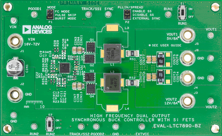
The LTC7890-BZ, manufactured by Analog Devices, is a high-performance synchronous step-down DC/DC controller designed for efficient and compact power supply solutions. It supports a wide input voltage range and employs advanced control techniques to deliver a stable and precise output voltage, even under dynamic load conditions. This component is ideal for applications requiring high efficiency, compact design, and robust performance.
Explore Projects Built with LTC7890-BZ


Explore Projects Built with LTC7890-BZ
Common Applications and Use Cases
- Industrial power supplies
- Automotive systems
- Telecommunications equipment
- Distributed power architectures
- High-performance computing systems
Technical Specifications
Key Technical Details
- Input Voltage Range: 4.5V to 60V
- Output Voltage Range: 0.8V to 24V
- Switching Frequency: Adjustable from 100kHz to 3MHz
- Efficiency: Up to 95% (depending on configuration)
- Output Current: Up to 25A (with appropriate external components)
- Control Mode: Current-mode or voltage-mode control
- Operating Temperature Range: -40°C to 125°C
- Package: 28-lead TSSOP (Thermally Enhanced)
Pin Configuration and Descriptions
The LTC7890-BZ is housed in a 28-lead TSSOP package. Below is the pin configuration and description:
| Pin Number | Pin Name | Description |
|---|---|---|
| 1 | VIN | Input supply voltage. Connect to the input power source. |
| 2 | VOUT | Output voltage sense pin. Connect to the output for feedback regulation. |
| 3 | FB | Feedback pin. Connect to a resistor divider to set the output voltage. |
| 4 | ITH | Compensation pin for loop stability. Connect to a capacitor and resistor. |
| 5 | RUN | Enable pin. Pull high to enable the controller. |
| 6 | SYNC | Synchronization input for external clock. |
| 7 | GND | Ground connection. |
| 8 | SW | Switch node connection to the inductor. |
| 9 | BOOST | Bootstrap capacitor connection for high-side MOSFET drive. |
| 10 | INTVCC | Internal regulator output. Connect a capacitor for stability. |
| 11 | PG | Power good indicator. Open-drain output. |
| 12 | SS | Soft-start pin. Connect a capacitor to control startup timing. |
| 13-28 | NC | No connection. Leave these pins unconnected. |
Usage Instructions
How to Use the LTC7890-BZ in a Circuit
Input and Output Connections:
- Connect the input voltage source to the VIN pin.
- Use a suitable inductor and capacitor at the output to filter the voltage and connect the load.
Setting the Output Voltage:
- Use a resistor divider network connected to the FB pin to set the desired output voltage. The formula is: [ V_{OUT} = V_{REF} \times \left(1 + \frac{R1}{R2}\right) ] where ( V_{REF} ) is typically 0.8V.
Compensation:
- Connect a capacitor and resistor to the ITH pin to stabilize the control loop. Refer to the datasheet for recommended values based on your application.
Soft-Start:
- Connect a capacitor to the SS pin to control the startup time. A larger capacitor results in a slower startup.
Synchronization:
- If required, connect an external clock to the SYNC pin to synchronize the switching frequency.
Enable the Controller:
- Pull the RUN pin high to enable the LTC7890-BZ. Use a resistor divider if you need to set a specific undervoltage lockout threshold.
Important Considerations and Best Practices
- Thermal Management: Ensure proper heat dissipation by using a PCB with adequate copper area around the VIN, SW, and GND pins.
- Input Capacitor: Use low-ESR capacitors at the input to minimize voltage ripple.
- Inductor Selection: Choose an inductor with sufficient current rating and low DC resistance to optimize efficiency.
- Output Capacitor: Select capacitors with low ESR to ensure stable operation and low output voltage ripple.
- PCB Layout: Follow the recommended layout guidelines in the datasheet to minimize noise and improve performance.
Example Code for Arduino UNO
The LTC7890-BZ can be used in conjunction with an Arduino UNO for monitoring or controlling its operation. Below is an example code snippet to monitor the power good (PG) signal:
// Define the pin connected to the PG (Power Good) signal
const int pgPin = 2; // Connect PG pin of LTC7890-BZ to Arduino digital pin 2

void setup() {
  pinMode(pgPin, INPUT); // Set PG pin as input
  Serial.begin(9600);    // Initialize serial communication
}

void loop() {
  int pgStatus = digitalRead(pgPin); // Read the PG signal

  if (pgStatus == HIGH) {
    // PG signal is high, output voltage is within regulation
    Serial.println("Power Good: Output voltage is stable.");
  } else {
    // PG signal is low, output voltage is out of regulation
    Serial.println("Warning: Output voltage is not stable!");
  }

  delay(1000); // Wait for 1 second before checking again
}
Troubleshooting and FAQs
Common Issues and Solutions
Output Voltage is Incorrect:
- Verify the resistor divider network connected to the FB pin.
- Check for proper connections and soldering on the PCB.
Controller Does Not Start:
- Ensure the RUN pin is pulled high.
- Check the input voltage to ensure it is within the specified range.
Excessive Output Ripple:
- Use low-ESR capacitors at the output.
- Verify the inductor value and ensure it meets the design requirements.
Overheating:
- Check for proper thermal management and ensure adequate PCB copper area.
- Verify that the input and output currents are within the specified limits.
FAQs
Q1: Can the LTC7890-BZ operate without an external clock?
A1: Yes, the LTC7890-BZ has an internal oscillator and does not require an external clock. However, you can synchronize it to an external clock using the SYNC pin if needed.
Q2: What is the maximum output current the LTC7890-BZ can handle?
A2: The maximum output current depends on the external components, such as the MOSFETs and inductor. With appropriate components, it can support up to 25A.
Q3: How do I calculate the soft-start time?
A3: The soft-start time can be calculated using the formula:
[
t_{SS} = \frac{C_{SS} \times V_{REF}}{I_{SS}}
]
where ( C_{SS} ) is the soft-start capacitor, ( V_{REF} ) is 0.8V, and ( I_{SS} ) is the soft-start charging current (refer to the datasheet for the exact value).
Q4: Can I use the LTC7890-BZ in automotive applications?
A4: Yes, the wide input voltage range and robust design make it suitable for automotive systems. Ensure compliance with automotive standards as required.