
How to Use AOZ3018PI 5A Buck Regulator (SO-8 Exposed Pad): Examples, Pinouts, and Specs
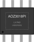
 Design with AOZ3018PI 5A Buck Regulator (SO-8 Exposed Pad) in Cirkit Designer
Introduction
The AOZ3018PI is a high-efficiency step-down (buck) voltage regulator manufactured by Alpha & Omega Semiconductor. It is capable of delivering up to 5A of continuous output current and is designed for compact, high-performance applications. The device features an exposed pad for enhanced thermal performance, making it suitable for applications requiring efficient heat dissipation. With its wide input voltage range and minimal external component requirements, the AOZ3018PI is ideal for powering microcontrollers, FPGAs, and other digital circuits.
Explore Projects Built with AOZ3018PI 5A Buck Regulator (SO-8 Exposed Pad)
 Open Project in Cirkit Designer
 Open Project in Cirkit Designer
 Open Project in Cirkit Designer
 Open Project in Cirkit Designer
Explore Projects Built with AOZ3018PI 5A Buck Regulator (SO-8 Exposed Pad)
Open Project in Cirkit DesignerOpen Project in Cirkit DesignerOpen Project in Cirkit DesignerOpen Project in Cirkit DesignerCommon Applications
- Consumer electronics (e.g., set-top boxes, TVs, and gaming consoles)
- Industrial equipment
- Networking devices
- Point-of-load power supplies
- Battery-powered systems
Technical Specifications
Key Technical Details
| Parameter | Value |
|---|---|
| Input Voltage Range | 4.5V to 18V |
| Output Voltage Range | 0.8V to 7V |
| Maximum Output Current | 5A |
| Switching Frequency | 500kHz |
| Efficiency | Up to 95% |
| Operating Temperature Range | -40°C to +85°C |
| Package Type | SO-8 Exposed Pad |
Pin Configuration and Descriptions
The AOZ3018PI is housed in an SO-8 package with an exposed pad for thermal management. Below is the pin configuration and description:
| Pin Number | Pin Name | Description |
|---|---|---|
| 1 | VIN | Input voltage supply (4.5V to 18V). Connect a decoupling capacitor close to this pin. |
| 2 | EN | Enable pin. Pull high to enable the regulator, or pull low to disable it. |
| 3 | COMP | Compensation pin. Connect a capacitor and resistor network for loop stability. |
| 4 | FB | Feedback pin. Connect to a resistor divider to set the output voltage. |
| 5 | GND | Ground pin. Connect to system ground. |
| 6 | LX | Switching node. Connect to the inductor. |
| 7 | LX | Switching node (same as Pin 6). Connect to the inductor. |
| 8 | BST | Bootstrap pin. Connect a capacitor between BST and LX for high-side MOSFET drive. |
| Exposed Pad | GND | Thermal pad. Connect to ground for heat dissipation. |
Usage Instructions
How to Use the AOZ3018PI in a Circuit
Input and Output Capacitors:
- Place a low-ESR ceramic capacitor (e.g., 10µF) close to the VIN pin to minimize input voltage ripple.
- Use an output capacitor (e.g., 22µF) to stabilize the output voltage and reduce ripple.
Inductor Selection:
- Choose an inductor with a saturation current rating higher than the maximum output current (5A).
- The recommended inductance value is between 1µH and 4.7µH, depending on the desired ripple current.
Feedback Resistor Divider:
- Use two resistors to set the output voltage. The formula is: [ V_{OUT} = 0.8V \times \left(1 + \frac{R1}{R2}\right) ] where R1 is connected between FB and VOUT, and R2 is connected between FB and GND.
Bootstrap Capacitor:
- Connect a 0.1µF ceramic capacitor between the BST and LX pins to drive the high-side MOSFET.
Enable Pin:
- Pull the EN pin high (e.g., connect to VIN) to enable the regulator. Pull it low to disable the output.
Thermal Considerations:
- Connect the exposed pad to a large ground plane for optimal heat dissipation.
- Use thermal vias to improve heat transfer to other PCB layers.
Example Circuit
Below is an example of how to connect the AOZ3018PI in a typical application:
VIN (12V) ----+----[10µF]---- GND
              |
              +----[AOZ3018PI VIN Pin]
                   [AOZ3018PI GND Pin]---- GND
                   [AOZ3018PI LX Pin]----+----[Inductor]----+---- VOUT (5V)
                                         |                 |
                                         +----[22µF]---- GND
Arduino UNO Example Code
The AOZ3018PI can be used to power an Arduino UNO. Below is an example code snippet to demonstrate how to use the regulator to power the Arduino and control the EN pin:
// Example code to control the AOZ3018PI EN pin using Arduino UNO

const int enablePin = 7; // Connect EN pin of AOZ3018PI to Arduino pin 7

void setup() {
  pinMode(enablePin, OUTPUT); // Set pin 7 as an output
  digitalWrite(enablePin, HIGH); // Enable the AOZ3018PI regulator
}

void loop() {
  // Toggle the regulator ON and OFF every 5 seconds
  digitalWrite(enablePin, HIGH); // Enable the regulator
  delay(5000); // Wait for 5 seconds
  digitalWrite(enablePin, LOW); // Disable the regulator
  delay(5000); // Wait for 5 seconds
}
Troubleshooting and FAQs
Common Issues and Solutions
Output Voltage is Incorrect:
- Verify the feedback resistor values. Ensure they are calculated correctly for the desired output voltage.
- Check for loose or incorrect connections on the FB pin.
Excessive Heat:
- Ensure the exposed pad is properly soldered to a ground plane with adequate thermal vias.
- Check if the input voltage or load current exceeds the specified limits.
Regulator Does Not Start:
- Confirm that the EN pin is pulled high. If left floating, the regulator will remain disabled.
- Verify the input voltage is within the 4.5V to 18V range.
High Output Ripple:
- Use low-ESR capacitors for both input and output.
- Ensure the inductor value is appropriate for the application.
FAQs
Q1: Can the AOZ3018PI operate without a heatsink?
A1: Yes, the exposed pad provides sufficient thermal dissipation for most applications. However, for high-current applications, ensure proper PCB design with thermal vias.
Q2: What happens if the EN pin is left floating?
A2: The regulator will remain disabled. Always pull the EN pin high to enable the device.
Q3: Can I use the AOZ3018PI for 3.3V output from a 12V input?
A3: Yes, use the appropriate feedback resistor values to set the output voltage to 3.3V.
Q4: Is the AOZ3018PI suitable for battery-powered applications?
A4: Yes, its high efficiency and wide input voltage range make it ideal for battery-powered systems.