How to Use AED6-R503-5V RGB LED DC5V: Examples, Pinouts, and Specs
Introduction
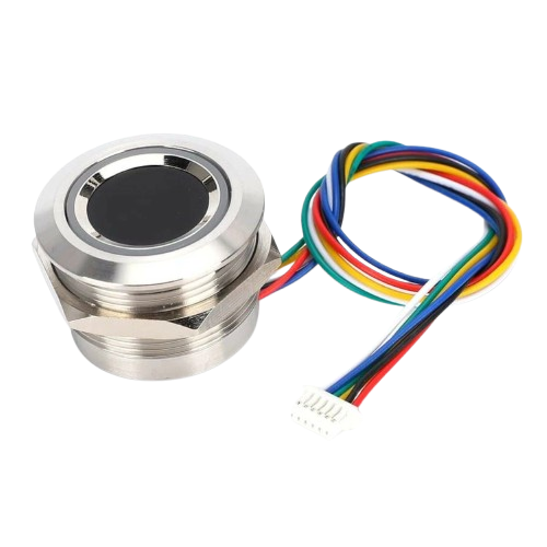
The AED6-R503-5V RGB LED, manufactured by GROW, is a versatile multi-color LED designed to operate at a standard 5V DC. This component combines red, green, and blue light-emitting diodes (LEDs) into a single package, allowing it to produce a wide range of colors through additive color mixing. It is ideal for applications requiring dynamic lighting effects, such as decorative lighting, status indicators, and DIY electronics projects.
Explore Projects Built with AED6-R503-5V RGB LED DC5V
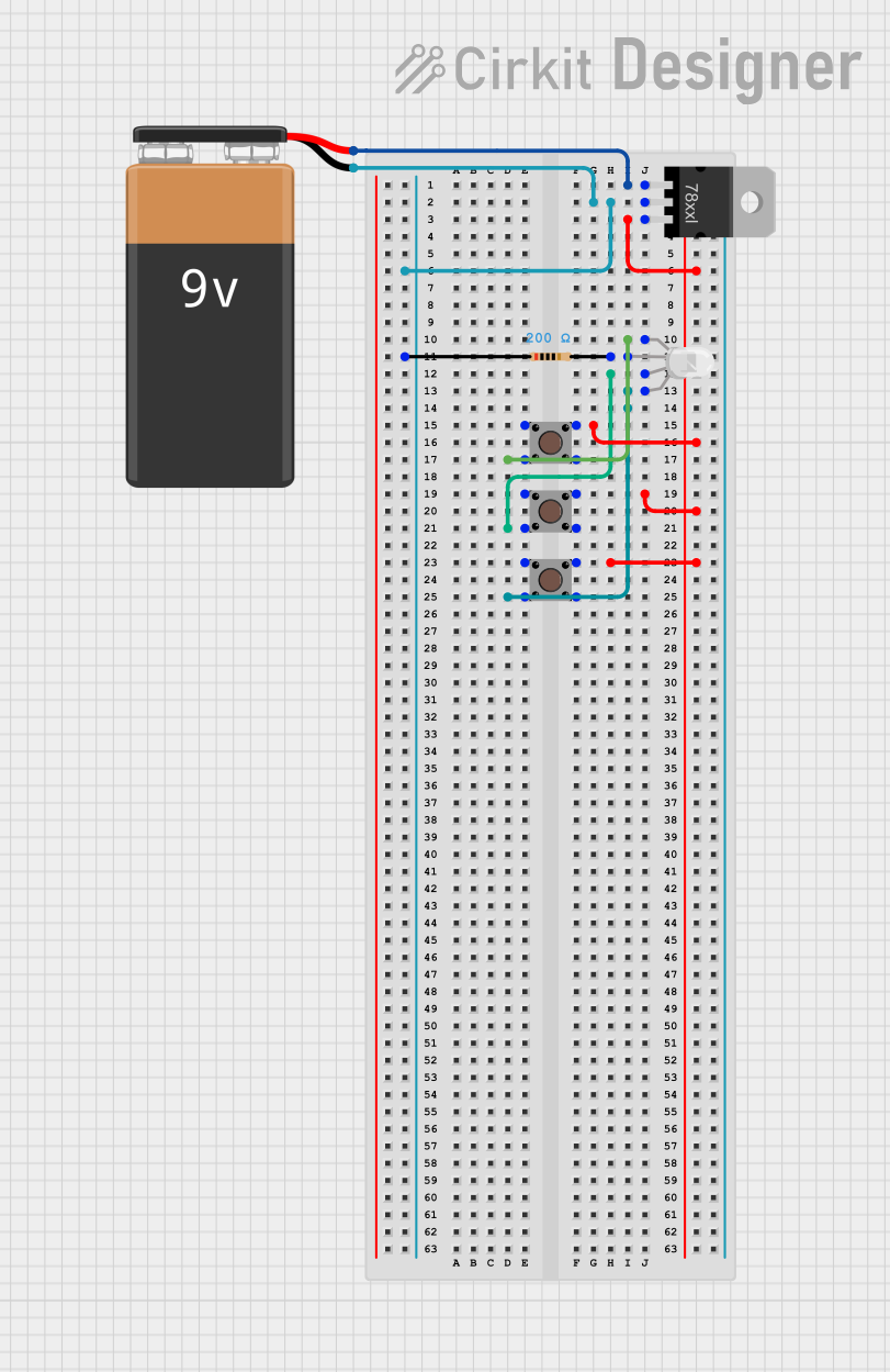
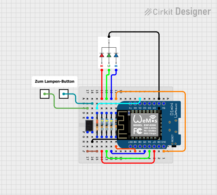

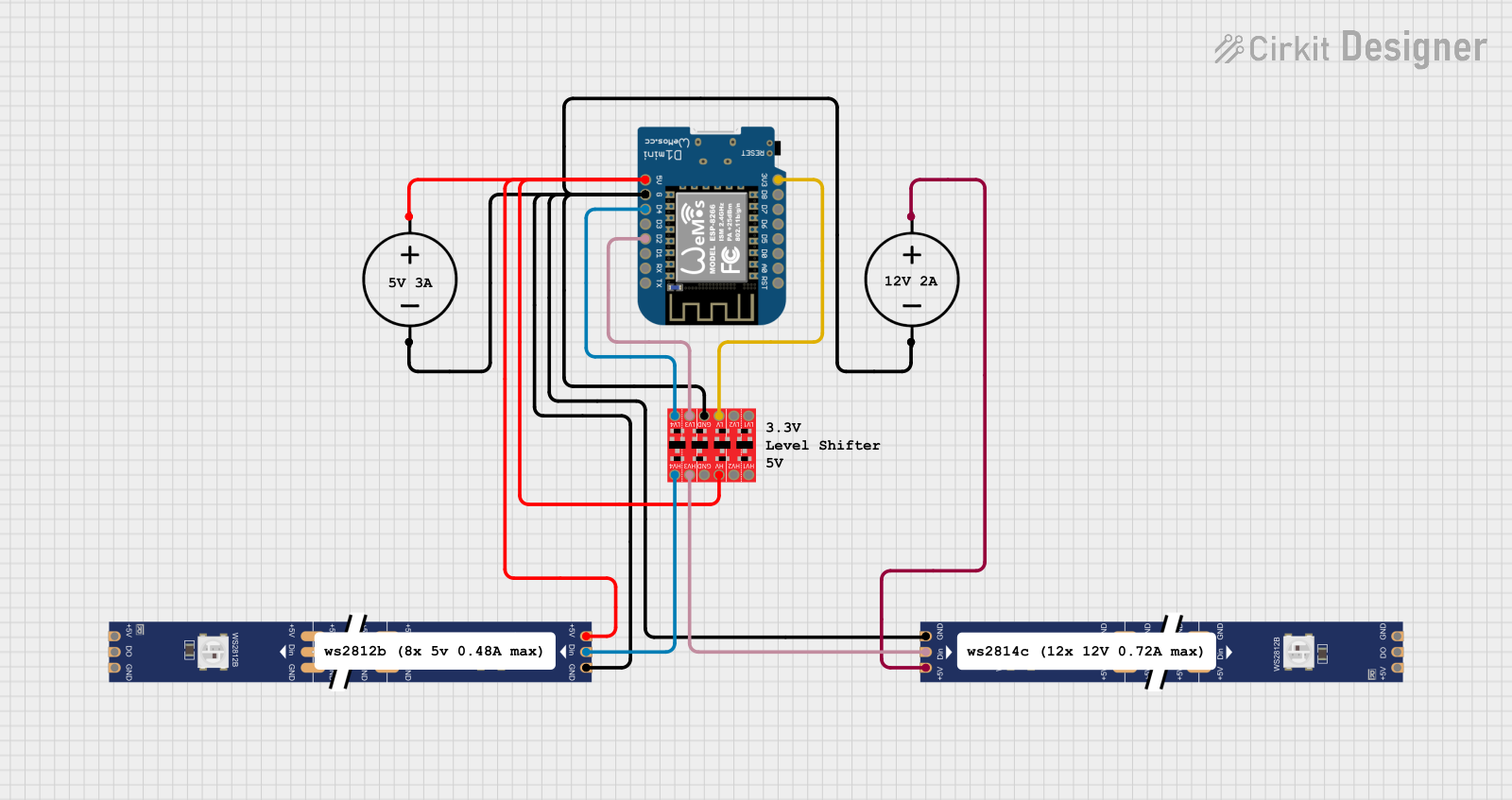
Explore Projects Built with AED6-R503-5V RGB LED DC5V
Common Applications
- Decorative and ambient lighting
- Status indicators for electronic devices
- DIY electronics and Arduino projects
- RGB displays and signage
- Prototyping and educational purposes
Technical Specifications
Below are the key technical details for the AED6-R503-5V RGB LED:
| Parameter | Value |
|---|---|
| Manufacturer | GROW |
| Part Number | AED6-R503-5V |
| Operating Voltage | 5V DC |
| Forward Current (per color) | 20mA (typical) |
| LED Colors | Red, Green, Blue |
| Viewing Angle | 120° |
| Luminous Intensity | Red: 600-800 mcd |
| Green: 1000-1200 mcd | |
| Blue: 400-500 mcd | |
| Package Type | 5mm round |
| Operating Temperature | -25°C to +85°C |
Pin Configuration
The AED6-R503-5V RGB LED has four pins: one common cathode (or anode, depending on the variant) and three individual pins for controlling the red, green, and blue LEDs. Below is the pinout description:
| Pin Number | Pin Name | Description |
|---|---|---|
| 1 | Red (R) | Controls the red LED. Connect to a current-limiting resistor. |
| 2 | Common Cathode | Common ground for all LEDs. |
| 3 | Green (G) | Controls the green LED. Connect to a current-limiting resistor. |
| 4 | Blue (B) | Controls the blue LED. Connect to a current-limiting resistor. |
Note: Ensure you verify whether your specific variant is common cathode or common anode before wiring.
Usage Instructions
How to Use the Component in a Circuit
- Power Supply: Connect the common cathode pin to the ground (GND) of your power supply. If using a common anode variant, connect it to the positive terminal (5V).
- Current Limiting Resistors: Use appropriate resistors (typically 220Ω to 330Ω) in series with the red, green, and blue pins to limit the current and prevent damage to the LEDs.
- Control: Apply a voltage signal to the red, green, and blue pins to control the brightness of each color. By varying the intensity of each color, you can create a wide range of colors.
Example Circuit with Arduino UNO
Below is an example of how to connect and control the AED6-R503-5V RGB LED using an Arduino UNO:
Circuit Diagram
- Connect the common cathode pin to the GND pin of the Arduino.
- Connect the Red (R) pin to Arduino digital pin 9 through a 220Ω resistor.
- Connect the Green (G) pin to Arduino digital pin 10 through a 220Ω resistor.
- Connect the Blue (B) pin to Arduino digital pin 11 through a 220Ω resistor.
Arduino Code
// Define the RGB LED pins
const int redPin = 9;   // Red LED connected to pin 9
const int greenPin = 10; // Green LED connected to pin 10
const int bluePin = 11;  // Blue LED connected to pin 11

void setup() {
  // Set the RGB LED pins as outputs
  pinMode(redPin, OUTPUT);
  pinMode(greenPin, OUTPUT);
  pinMode(bluePin, OUTPUT);
}

void loop() {
  // Example: Cycle through red, green, and blue colors
  setColor(255, 0, 0); // Red
  delay(1000);         // Wait 1 second
  setColor(0, 255, 0); // Green
  delay(1000);         // Wait 1 second
  setColor(0, 0, 255); // Blue
  delay(1000);         // Wait 1 second
  setColor(255, 255, 0); // Yellow (Red + Green)
  delay(1000);           // Wait 1 second
}

// Function to set the RGB LED color
void setColor(int redValue, int greenValue, int blueValue) {
  analogWrite(redPin, redValue);   // Set red brightness
  analogWrite(greenPin, greenValue); // Set green brightness
  analogWrite(bluePin, blueValue);  // Set blue brightness
}
Important Considerations and Best Practices
- Always use current-limiting resistors to prevent excessive current from damaging the LEDs.
- Verify the common cathode or anode configuration of your LED before wiring.
- Avoid exceeding the maximum forward current (20mA per color) to ensure the longevity of the component.
- Use PWM (Pulse Width Modulation) to control the brightness of each color for smooth color transitions.
Troubleshooting and FAQs
Common Issues and Solutions
LED Not Lighting Up
- Cause: Incorrect wiring or missing current-limiting resistors.
- Solution: Double-check the wiring and ensure resistors are connected in series with each LED pin.
Incorrect Colors Displayed
- Cause: Miswiring of the red, green, and blue pins.
- Solution: Verify the pin connections and ensure they match the Arduino code.
LED Flickering
- Cause: Insufficient power supply or unstable PWM signals.
- Solution: Use a stable 5V power source and ensure proper PWM signal generation.
LED Overheating
- Cause: Excessive current due to missing or low-value resistors.
- Solution: Use appropriate resistors (220Ω to 330Ω) to limit the current.
FAQs
Q: Can I use the AED6-R503-5V RGB LED with a 3.3V microcontroller?
A: Yes, but the brightness may be reduced. Ensure the forward voltage of each LED color is met, and adjust resistor values accordingly.
Q: How do I create custom colors?
A: Use PWM to vary the intensity of the red, green, and blue LEDs. By mixing different brightness levels, you can create a wide range of colors.
Q: Is the AED6-R503-5V waterproof?
A: No, this component is not waterproof. For outdoor or wet environments, use a waterproof enclosure.
Q: Can I connect the LED directly to a power source without resistors?
A: No, doing so may damage the LED due to excessive current. Always use current-limiting resistors.
This concludes the documentation for the AED6-R503-5V RGB LED DC5V.