How to Use polulu micro maestro: Examples, Pinouts, and Specs
Introduction
The Pololu Micro Maestro is a compact and versatile servo controller designed for precise control of multiple servos. It supports a simple serial interface and includes built-in scripting capabilities, making it an excellent choice for robotics, automation, and animatronics projects. With its small size and powerful features, the Micro Maestro is ideal for applications requiring precise and synchronized servo movements.
Explore Projects Built with polulu micro maestro


Explore Projects Built with polulu micro maestro
Common Applications and Use Cases
- Robotics: Control of robotic arms, grippers, and walking mechanisms.
- Animatronics: Creating lifelike movements in models or displays.
- Automation: Controlling servos in industrial or home automation systems.
- Prototyping: Rapid development of servo-based projects.
- Educational projects: Teaching servo control and scripting concepts.
Technical Specifications
The Pololu Micro Maestro is available in 6-channel, 12-channel, and 18-channel versions. Below are the key technical details:
General Specifications
| Parameter | Value |
|---|---|
| Input Voltage Range | 5–16 V |
| Logic Voltage | 5 V |
| Servo Channels | 6, 12, or 18 (depending on model) |
| Communication Interfaces | USB, TTL Serial, and I²C |
| Current Consumption | 40 mA (typical, excluding servos) |
| Dimensions | 30 mm × 18 mm × 7 mm |
| Weight | 2 g |
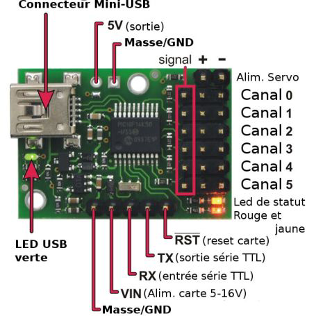
Pin Configuration and Descriptions
| Pin Name | Description |
|---|---|
| VIN | Power input for the servos (5–16 V). |
| GND | Ground connection. |
| Channel Pins | Servo signal output pins (6, 12, or 18 depending on the model). |
| USB | USB interface for configuration and control. |
| TX | TTL serial transmit pin for communication with a microcontroller. |
| RX | TTL serial receive pin for communication with a microcontroller. |
| RST | Reset pin to restart the controller. |
Usage Instructions
How to Use the Pololu Micro Maestro in a Circuit
- Power the Controller: Connect a power source (5–16 V) to the VIN and GND pins. Ensure the power supply can handle the current requirements of all connected servos.
- Connect Servos: Attach the servo signal wires to the channel pins. Connect the servo power and ground wires to the same power source as the controller.
- Communication Setup:
- For USB control, connect the Micro Maestro to a computer using a USB cable.
- For TTL serial control, connect the TX and RX pins to the corresponding pins on a microcontroller (e.g., Arduino).
- Configuration: Use the Pololu Maestro Control Center software to configure servo settings, create sequences, or write scripts.
- Control: Send commands via USB, TTL serial, or I²C to control the servos.
Important Considerations and Best Practices
- Power Supply: Use a power supply capable of providing sufficient current for all connected servos. A separate power supply for servos is recommended for high-current applications.
- Signal Interference: Keep servo signal wires short to minimize noise and interference.
- Heat Management: Avoid overloading the controller to prevent overheating.
- Firmware Updates: Check for firmware updates on the Pololu website to ensure compatibility and access to the latest features.
Example: Using the Micro Maestro with Arduino UNO
Below is an example of controlling a servo connected to the Micro Maestro using an Arduino UNO via TTL serial communication.
#include <SoftwareSerial.h>

// Define the RX and TX pins for SoftwareSerial
SoftwareSerial maestroSerial(10, 11); // RX = pin 10, TX = pin 11

void setup() {
  maestroSerial.begin(9600); // Set baud rate to 9600 for communication
}

void setServoTarget(uint8_t channel, uint16_t target) {
  // Sends a command to set the target position of a servo
  // Channel: Servo channel (0–5 for 6-channel version)
  // Target: Position in quarter-microseconds (e.g., 6000 = 1500 µs)
  maestroSerial.write(0x84);          // Command byte for setting target
  maestroSerial.write(channel);      // Servo channel
  maestroSerial.write(target & 0x7F); // Lower 7 bits of target
  maestroSerial.write(target >> 7 & 0x7F); // Upper 7 bits of target
}

void loop() {
  setServoTarget(0, 6000); // Move servo on channel 0 to 1500 µs position
  delay(1000);             // Wait for 1 second
  setServoTarget(0, 7000); // Move servo on channel 0 to 1750 µs position
  delay(1000);             // Wait for 1 second
}
Troubleshooting and FAQs
Common Issues and Solutions
Servos Not Moving:
- Ensure the power supply is connected and provides sufficient voltage and current.
- Verify that the servo signal wires are connected to the correct channel pins.
- Check the configuration in the Pololu Maestro Control Center.
Communication Problems:
- For USB communication, ensure the correct drivers are installed.
- For TTL serial communication, verify the baud rate and connections (TX to RX and RX to TX).
Overheating:
- Reduce the number of servos or use a separate power supply for high-current applications.
- Ensure proper ventilation around the controller.
Unexpected Movements:
- Check for noise or interference in the signal wires.
- Verify that the servo targets are within the valid range for your servos.
FAQs
Q: Can I control the Micro Maestro with a Raspberry Pi?
A: Yes, the Micro Maestro can be controlled via USB or TTL serial communication with a Raspberry Pi. Use the appropriate libraries or scripts to send commands.
Q: How many servos can I control with the Micro Maestro?
A: The Micro Maestro is available in 6-channel, 12-channel, and 18-channel versions, allowing control of up to 18 servos.
Q: Can I use the Micro Maestro without a computer or microcontroller?
A: Yes, the Micro Maestro has built-in scripting capabilities, allowing it to run standalone sequences without an external controller.
Q: What is the maximum servo pulse range supported?
A: The Micro Maestro supports a pulse range of 64–3280 µs, but most servos operate within 1000–2000 µs. Always check your servo's specifications.