How to Use relay: Examples, Pinouts, and Specs
Introduction
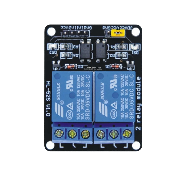
A relay is an electromechanical switch that uses an electromagnetic coil to open or close a circuit. It allows a low-power signal to control high-power devices, making it an essential component in automation, control systems, and power management. Relays are widely used in applications such as home automation, motor control, industrial equipment, and automotive systems.
Common use cases include:
- Switching high-current loads like motors, lights, and heaters.
- Isolating control circuits from high-power circuits for safety.
- Enabling remote control of devices in IoT and automation systems.
Explore Projects Built with relay


Explore Projects Built with relay
Technical Specifications
Below are the general technical specifications for a standard single-pole single-throw (SPST) relay. Specifications may vary depending on the specific relay model.
General Specifications
- Coil Voltage: 5V, 12V, or 24V DC (common options)
- Coil Current: Typically 30-100 mA
- Contact Rating: 10A at 250V AC or 10A at 30V DC
- Contact Type: SPST (Single Pole Single Throw) or SPDT (Single Pole Double Throw)
- Switching Time: 5-15 ms (typical)
- Dielectric Strength: 1000V AC (between coil and contacts)
- Insulation Resistance: >100 MΩ at 500V DC
Pin Configuration
The pin configuration of a typical 5V SPDT relay is as follows:
| Pin Name | Description |
|---|---|
| Coil (+) | Positive terminal of the electromagnetic coil. |
| Coil (-) | Negative terminal of the electromagnetic coil. |
| Common (COM) | Common terminal connected to the moving part of the switch. |
| Normally Open (NO) | Terminal that is disconnected from COM when the relay is inactive. |
| Normally Closed (NC) | Terminal that is connected to COM when the relay is inactive. |
Usage Instructions
How to Use a Relay in a Circuit
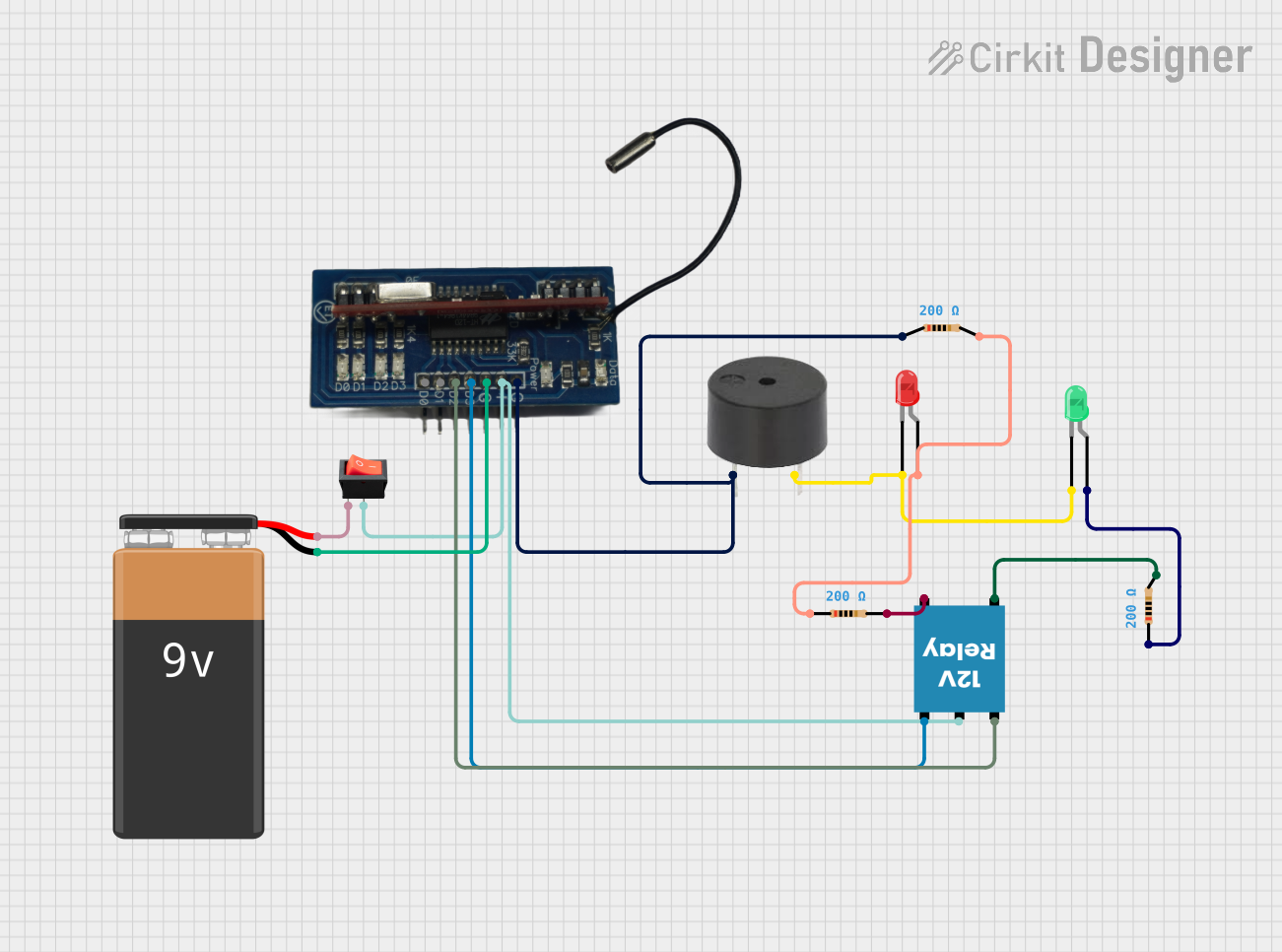
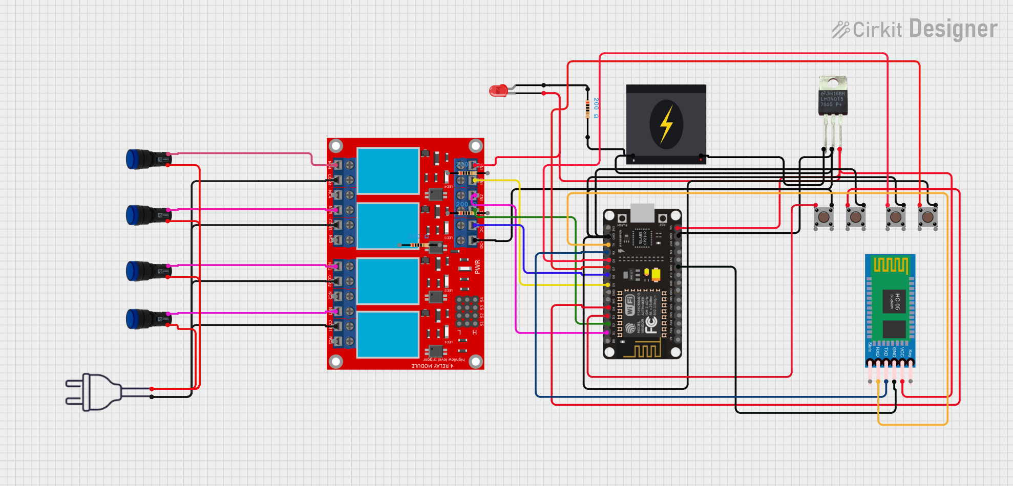
- Power the Coil: Connect the relay's coil terminals to a power source that matches the relay's rated coil voltage (e.g., 5V DC for a 5V relay). Use a transistor or MOSFET to drive the coil if the control signal cannot supply enough current.
- Control the Load: Connect the load (e.g., motor, light) to the relay's COM and NO or NC terminals, depending on whether you want the load to be normally off or normally on.
- Add a Flyback Diode: Place a flyback diode (e.g., 1N4007) across the coil terminals to protect the driving circuit from voltage spikes caused by the collapsing magnetic field when the relay is turned off.
- Control the Relay: Use a microcontroller, switch, or other control signal to activate the relay by energizing the coil.
Example Circuit with Arduino UNO
Below is an example of how to control a 5V relay using an Arduino UNO:
// Example: Controlling a 5V relay with Arduino UNO
// Pin 7 is connected to the relay module's control pin

const int relayPin = 7; // Define the pin connected to the relay module

void setup() {
  pinMode(relayPin, OUTPUT); // Set the relay pin as an output
  digitalWrite(relayPin, LOW); // Ensure the relay is off at startup
}

void loop() {
  digitalWrite(relayPin, HIGH); // Turn the relay on
  delay(1000); // Keep the relay on for 1 second
  digitalWrite(relayPin, LOW); // Turn the relay off
  delay(1000); // Keep the relay off for 1 second
}
Important Considerations
- Voltage Matching: Ensure the relay's coil voltage matches the control circuit's output voltage.
- Current Handling: Verify that the relay's contact rating is sufficient for the load's current and voltage.
- Isolation: Use optocouplers or isolation circuits if the relay is controlling high-voltage devices.
- Heat Dissipation: Avoid exceeding the relay's rated current to prevent overheating.
Troubleshooting and FAQs
Common Issues
Relay Not Activating:
- Check if the coil voltage matches the relay's rated voltage.
- Ensure the control circuit can supply enough current to energize the coil.
- Verify the connections to the relay's coil terminals.
Load Not Switching:
- Confirm the load is connected to the correct terminals (COM, NO, or NC).
- Check if the relay's contact rating is sufficient for the load.
- Inspect for loose or faulty wiring.
Relay Buzzing or Clicking:
- Ensure the control signal is stable and not fluctuating.
- Check for insufficient coil voltage or current.
Damaged Relay:
- Verify that the relay is not exposed to voltages or currents beyond its rated limits.
- Ensure a flyback diode is installed to protect the relay from voltage spikes.
FAQs
Q: Can I use a relay to control an AC load with a DC control signal?
A: Yes, relays are designed to isolate the control circuit from the load circuit, allowing you to control AC loads with a DC signal.
Q: Why is a flyback diode necessary?
A: A flyback diode protects the control circuit from voltage spikes generated when the relay's coil is de-energized. Without it, the voltage spike could damage the driving circuit.
Q: Can I use a relay to switch high-frequency signals?
A: Relays are not suitable for high-frequency switching due to their mechanical nature. Use solid-state relays (SSRs) or transistors for high-frequency applications.
Q: How do I know if my relay is SPST or SPDT?
A: Check the relay's datasheet or inspect the pin configuration. SPST relays have two contact terminals (COM and NO or NC), while SPDT relays have three (COM, NO, and NC).