How to Use Thermocouple 2 Pins: Examples, Pinouts, and Specs
Introduction
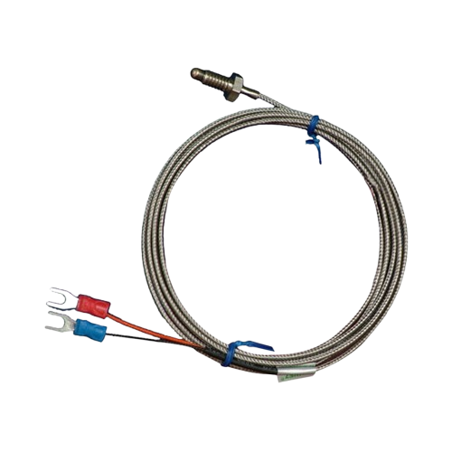
A thermocouple is a temperature-sensing device that operates based on the Seebeck effect, where a voltage is generated due to the temperature difference between two junctions of dissimilar metals. The "Thermocouple 2 Pins" is a simple, compact thermocouple with two pins for easy integration into electronic circuits. It is widely used for accurate temperature measurement in industrial, scientific, and DIY applications.
Explore Projects Built with Thermocouple 2 Pins

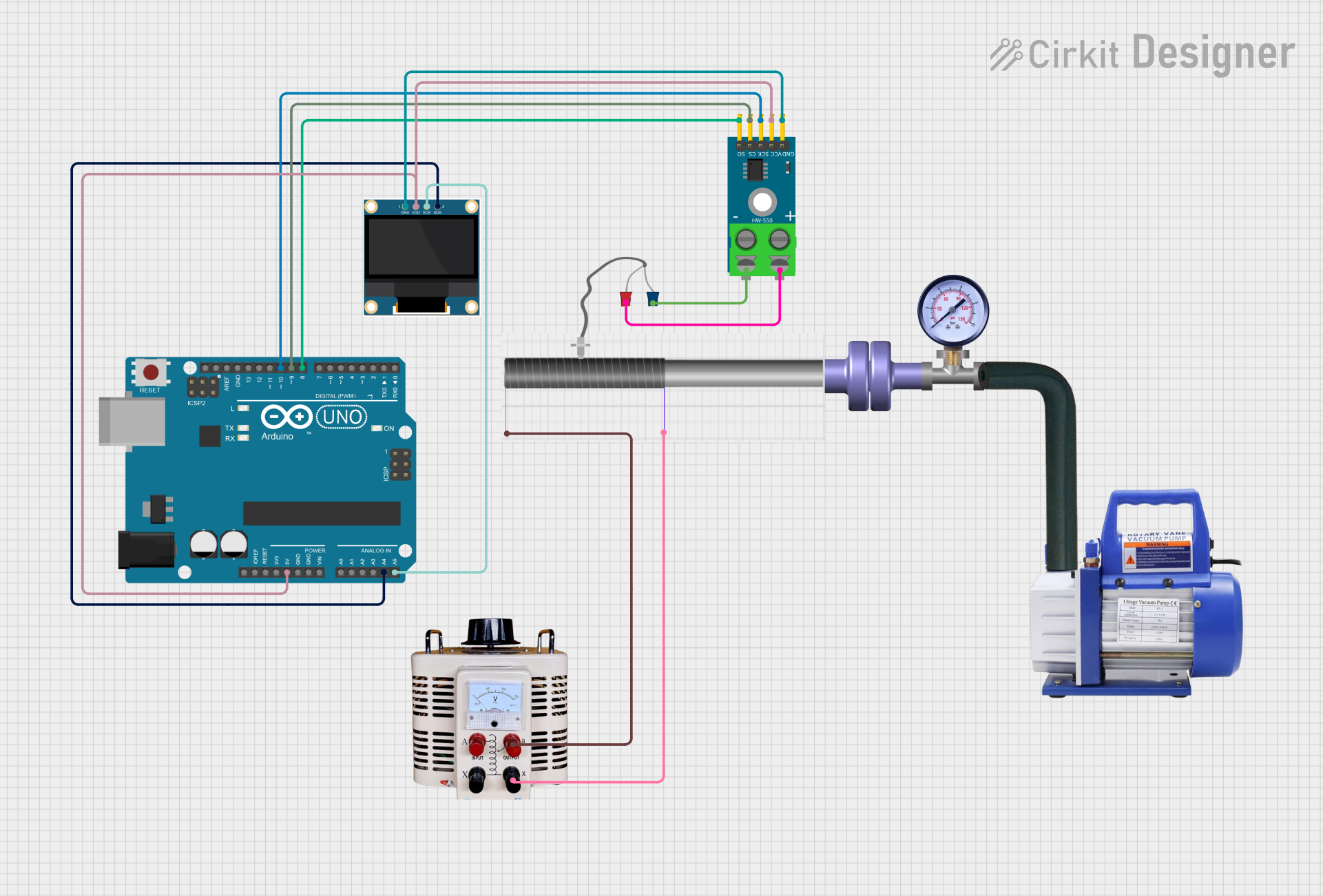
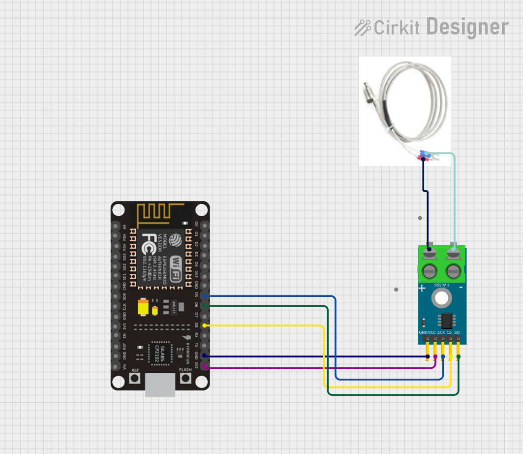
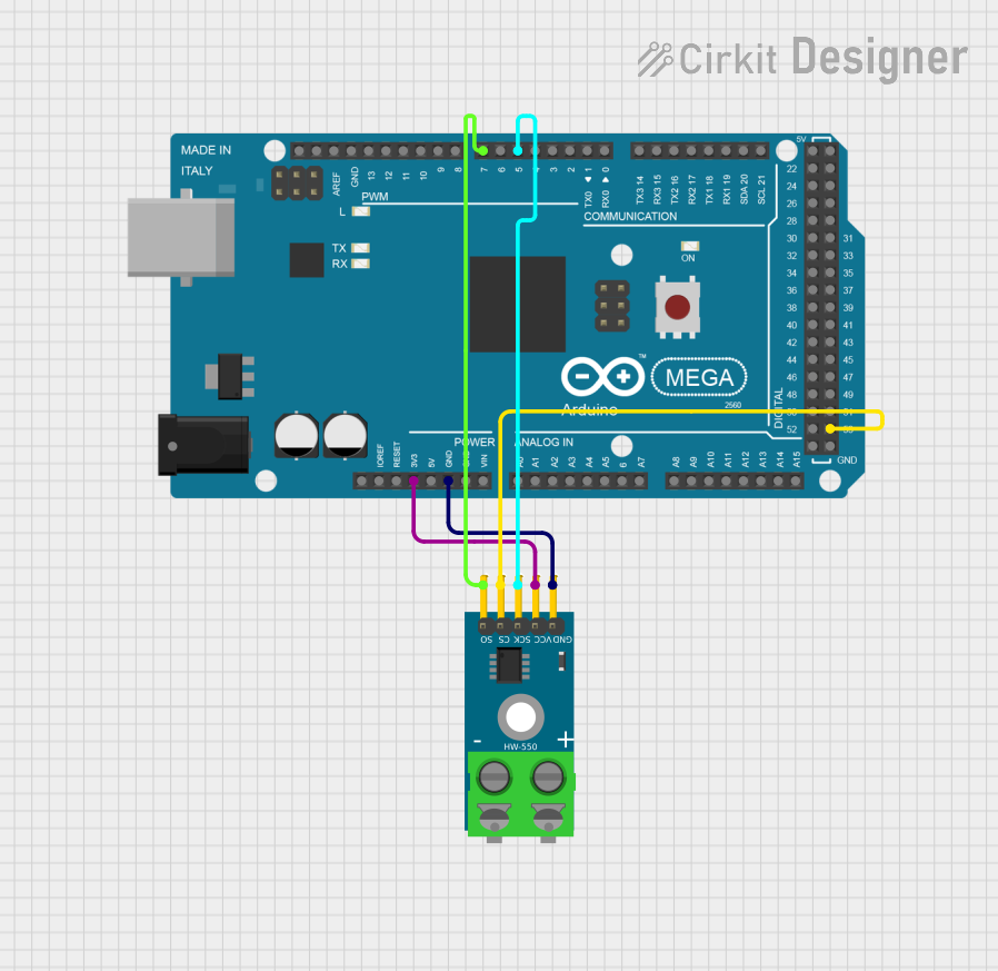
Explore Projects Built with Thermocouple 2 Pins
Common Applications and Use Cases
- Industrial temperature monitoring (e.g., furnaces, kilns)
- Scientific experiments requiring precise temperature readings
- Home appliances like ovens and water heaters
- DIY electronics projects involving temperature sensing
- Automotive and aerospace temperature diagnostics
Technical Specifications
The following table outlines the key technical details of the Thermocouple 2 Pins:
| Parameter | Specification |
|---|---|
| Type | Varies (e.g., Type K, Type J, etc.) |
| Temperature Range | -200°C to 1250°C (depending on type) |
| Output Voltage Range | Typically in microvolts (µV) |
| Accuracy | ±1°C to ±2°C (depending on calibration) |
| Response Time | Fast (milliseconds to seconds) |
| Connector Type | 2-pin (positive and negative leads) |
| Material | Dissimilar metals (varies by type) |
Pin Configuration and Descriptions
The Thermocouple 2 Pins has a simple pinout:
| Pin Number | Pin Name | Description |
|---|---|---|
| 1 | Positive | Positive lead (varies by thermocouple type) |
| 2 | Negative | Negative lead (varies by thermocouple type) |
Note: The polarity of the pins is critical for accurate temperature readings. Ensure proper connection to the circuit.
Usage Instructions
How to Use the Thermocouple in a Circuit
Connect the Thermocouple to an Amplifier or ADC:
Since thermocouples generate very small voltages, you need a thermocouple amplifier (e.g., MAX31855 or MAX6675) or an analog-to-digital converter (ADC) to read the signal accurately.Connect the Amplifier to a Microcontroller:
Use a microcontroller like an Arduino UNO to process the amplified signal and convert it into a temperature reading.Power the Circuit:
Ensure the amplifier and microcontroller are powered according to their specifications (e.g., 5V for Arduino UNO).Read and Process the Data:
Use the microcontroller to read the voltage from the thermocouple and convert it into a temperature value using the appropriate formula or library.
Important Considerations and Best Practices
- Polarity Matters: Always connect the positive and negative leads correctly to avoid incorrect readings.
- Cold Junction Compensation: Use an amplifier with built-in cold junction compensation to account for ambient temperature variations.
- Shielding: For noisy environments, use shielded cables to minimize interference.
- Calibration: Periodically calibrate the thermocouple for accurate measurements.
- Avoid Overheating: Do not expose the thermocouple to temperatures beyond its rated range.
Example Code for Arduino UNO
Below is an example of how to use a Type K thermocouple with a MAX6675 amplifier and an Arduino UNO:
#include "max6675.h" // Include the MAX6675 library

// Define the pins connected to the MAX6675 module
int thermoDO = 4;  // Data Out pin
int thermoCS = 5;  // Chip Select pin
int thermoCLK = 6; // Clock pin

// Create a MAX6675 object
MAX6675 thermocouple(thermoCLK, thermoCS, thermoDO);

void setup() {
  Serial.begin(9600); // Initialize serial communication
  Serial.println("Thermocouple Test");
  delay(500); // Allow time for the thermocouple to stabilize
}

void loop() {
  // Read the temperature from the thermocouple
  double temperature = thermocouple.readCelsius();

  // Check if the reading is valid
  if (isnan(temperature)) {
    Serial.println("Error: Thermocouple not connected!");
  } else {
    // Print the temperature to the Serial Monitor
    Serial.print("Temperature: ");
    Serial.print(temperature);
    Serial.println(" °C");
  }

  delay(1000); // Wait 1 second before the next reading
}
Note: Ensure the MAX6675 library is installed in your Arduino IDE before uploading the code.
Troubleshooting and FAQs
Common Issues and Solutions
No Temperature Reading or NAN Output:
- Cause: Loose or incorrect connections.
- Solution: Verify that the thermocouple leads are securely connected to the amplifier and that the amplifier is properly connected to the microcontroller.
Inaccurate Temperature Readings:
- Cause: Incorrect polarity or lack of cold junction compensation.
- Solution: Double-check the polarity of the thermocouple leads and use an amplifier with cold junction compensation.
Fluctuating or Noisy Readings:
- Cause: Electrical noise or interference.
- Solution: Use shielded cables and ensure proper grounding in the circuit.
Thermocouple Not Working at High Temperatures:
- Cause: Exceeding the thermocouple's temperature range.
- Solution: Verify the thermocouple's type and ensure it is rated for the temperature being measured.
FAQs
Q: Can I connect the thermocouple directly to an Arduino?
A: No, the voltage generated by a thermocouple is too small for direct measurement. You need an amplifier like the MAX6675 or MAX31855.
Q: How do I identify the positive and negative leads?
A: The positive lead is usually made of a specific metal (e.g., Chromel for Type K) and may have a color-coded insulation. Refer to the thermocouple's datasheet for details.
Q: Can I use the thermocouple in a humid environment?
A: Yes, but ensure the thermocouple is properly insulated and protected to prevent corrosion or short circuits.
Q: How often should I calibrate the thermocouple?
A: Calibration frequency depends on usage, but annual calibration is recommended for most applications.