How to Use PPK2: Examples, Pinouts, and Specs
Introduction
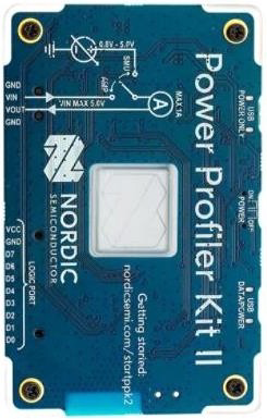
The PPK2 (Power Profiler Kit 2) is a versatile and programmable power supply module developed by Nordic Semiconductor. It is designed for testing, measuring, and powering electronic circuits with precision. The PPK2 is particularly useful for developers working on low-power devices, as it provides detailed power consumption analysis and supports adjustable voltage and current outputs.
Explore Projects Built with PPK2
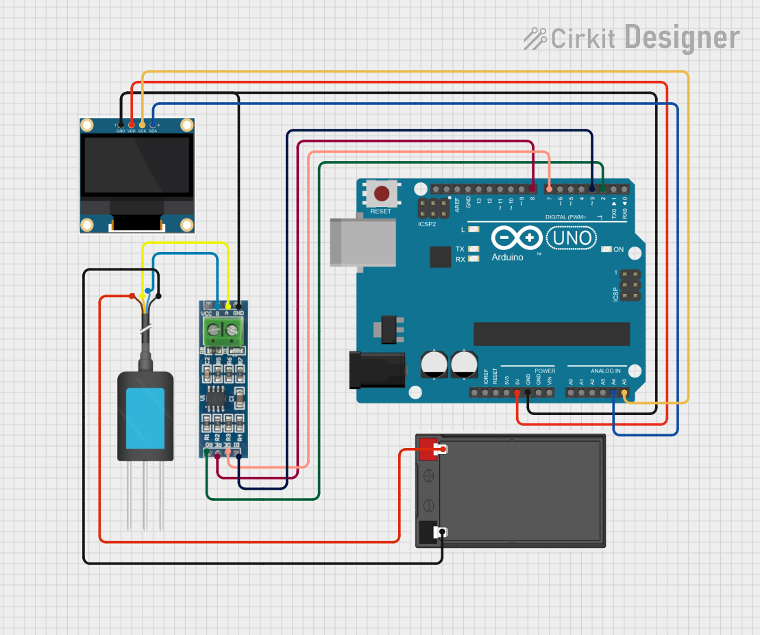

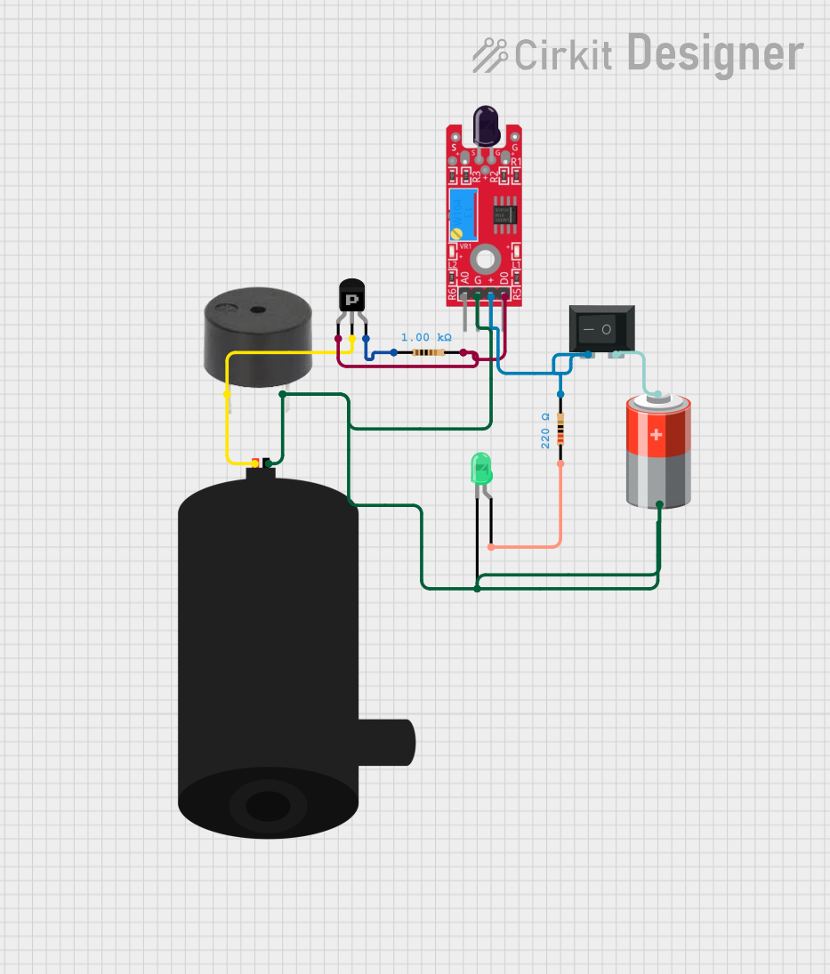

Explore Projects Built with PPK2
Common Applications and Use Cases
- Power profiling and consumption analysis for IoT devices
- Testing and debugging low-power embedded systems
- Prototyping circuits with adjustable power supply needs
- Measuring current consumption in microcontrollers and sensors
- Educational purposes for understanding power usage in electronics
Technical Specifications
The PPK2 is a feature-rich tool with the following key specifications:
| Parameter | Specification |
|---|---|
| Input Voltage Range | 2.0 V to 5.0 V (via USB) |
| Output Voltage Range | 0.8 V to 5.0 V (programmable) |
| Current Measurement Range | 100 nA to 1 A |
| Measurement Resolution | Down to 100 nA |
| Sampling Rate | Up to 100 kHz |
| Communication Interface | USB (for power and data transfer) |
| Supported Software | nRF Connect for Desktop (Power Profiler App) |
| Dimensions | 85 mm x 60 mm x 15 mm |
Pin Configuration and Descriptions
The PPK2 features several connectors and pins for interfacing with external circuits. Below is a description of the key pins and connectors:
| Pin/Connector | Description |
|---|---|
| VOUT+ | Positive output voltage terminal for powering the target circuit. |
| VOUT- | Negative output voltage terminal (ground) for the target circuit. |
| GND | Ground connection for external measurement or reference. |
| MEAS+ | Positive terminal for current measurement in external circuits. |
| MEAS- | Negative terminal for current measurement in external circuits. |
| USB-C Port | Used for power input and communication with a PC. |
| Switch | Toggles between "Source Meter" and "Ampere Meter" modes. |
Usage Instructions
The PPK2 is designed to be user-friendly and integrates seamlessly with Nordic Semiconductor's nRF Connect for Desktop software. Follow these steps to use the PPK2 effectively:
Setting Up the PPK2
- Install the Software: Download and install the nRF Connect for Desktop application from the Nordic Semiconductor website. Install the "Power Profiler" app within the software.
- Connect the PPK2: Use a USB-C cable to connect the PPK2 to your computer. Ensure the USB port provides sufficient power.
- Launch the Software: Open the Power Profiler app and select the connected PPK2 device.
Using the PPK2 in a Circuit
- Select the Mode: Use the switch on the PPK2 to choose between:
- Source Meter Mode: Supplies power to the target circuit and measures current.
- Ampere Meter Mode: Measures current in an externally powered circuit.
- Connect the Circuit:
- In Source Meter Mode, connect the target circuit to the
VOUT+andVOUT-terminals. - In Ampere Meter Mode, connect the circuit's power source to
MEAS+andMEAS-.
- In Source Meter Mode, connect the target circuit to the
- Configure Voltage and Current: Use the Power Profiler app to set the desired output voltage and current limits.
- Start Profiling: Begin the measurement process in the software. The app will display real-time current and voltage data, along with power consumption graphs.
Example: Using PPK2 with an Arduino UNO
To measure the power consumption of an Arduino UNO, follow these steps:
- Set the PPK2 to Source Meter Mode.
- Connect the
VOUT+terminal to the Arduino's 5V pin and theVOUT-terminal to the GND pin. - Configure the output voltage to 5.0 V in the Power Profiler app.
- Power the Arduino UNO and monitor its current consumption in the app.
Optional: Arduino Code for Testing
You can upload the following code to the Arduino UNO to simulate a simple power consumption scenario:
// Blink LED on pin 13 to observe power consumption
void setup() {
  pinMode(13, OUTPUT); // Set pin 13 as an output
}

void loop() {
  digitalWrite(13, HIGH); // Turn the LED on
  delay(1000);            // Wait for 1 second
  digitalWrite(13, LOW);  // Turn the LED off
  delay(1000);            // Wait for 1 second
}
Best Practices
- Always ensure the PPK2 is properly connected to avoid damaging the device or the target circuit.
- Use the appropriate mode (Source Meter or Ampere Meter) for your application.
- Avoid exceeding the maximum current rating of 1 A to prevent overheating or damage.
- Regularly update the nRF Connect for Desktop software to access the latest features and bug fixes.
Troubleshooting and FAQs
Common Issues and Solutions
PPK2 Not Detected by Software:
- Ensure the USB-C cable is properly connected.
- Verify that the nRF Connect for Desktop software is installed and up to date.
- Try using a different USB port or cable.
Incorrect Voltage Output:
- Check the voltage settings in the Power Profiler app.
- Ensure the target circuit is not drawing more current than the configured limit.
No Current Measurement in Ampere Meter Mode:
- Verify that the external power source is connected to
MEAS+andMEAS-. - Ensure the circuit is powered and functioning correctly.
- Verify that the external power source is connected to
Overheating or Shutdown:
- Reduce the current draw of the target circuit.
- Ensure adequate ventilation around the PPK2.
FAQs
Q: Can the PPK2 measure power consumption for battery-powered devices?
A: Yes, in Ampere Meter mode, the PPK2 can measure current consumption in externally powered circuits, including battery-powered devices.
Q: What is the maximum sampling rate of the PPK2?
A: The PPK2 supports a maximum sampling rate of 100 kHz, providing high-resolution power measurements.
Q: Is the PPK2 compatible with macOS and Linux?
A: Yes, the nRF Connect for Desktop software is available for Windows, macOS, and Linux.
Q: Can I use the PPK2 to power high-current devices?
A: The PPK2 is designed for low-power applications and supports a maximum current of 1 A. For higher currents, consider using an external power supply.
By following this documentation, users can effectively utilize the PPK2 for power profiling and circuit testing, ensuring accurate and reliable results.