How to Use ats: Examples, Pinouts, and Specs
Introduction
An Automatic Transfer Switch (ATS) is a critical device used in power management systems. It automatically transfers a power load from a primary power source (e.g., utility power) to a secondary source (e.g., a backup generator) in the event of a power outage or failure. Once the primary source is restored, the ATS switches the load back to it, ensuring uninterrupted power supply.
Explore Projects Built with ats


Explore Projects Built with ats
Common Applications and Use Cases
- Backup power systems for residential, commercial, and industrial facilities.
- Data centers and server rooms requiring continuous power.
- Hospitals and healthcare facilities to maintain life-support systems.
- Telecommunications and broadcasting stations.
- Critical infrastructure such as airports and water treatment plants.
Technical Specifications
Below are the general technical specifications for a typical ATS. Note that specific models may vary, so always refer to the manufacturer's datasheet for exact details.
Key Technical Details
- Voltage Rating: 120V to 480V AC (varies by model)
- Current Rating: 30A to 4000A
- Frequency: 50Hz or 60Hz
- Switching Time: Typically 1-10 seconds
- Control Voltage: 12V DC, 24V DC, or 230V AC (depending on the control circuit)
- Operating Temperature: -20°C to 60°C
- Enclosure Rating: IP20 to IP65 (depending on the environment)
Pin Configuration and Descriptions
The ATS typically has terminals for power input, output, and control signals. Below is a general pin configuration:
| Pin/Terminal | Description |
|---|---|
| L1 (Primary) | Line input from the primary power source (utility). |
| L2 (Secondary) | Line input from the secondary power source (generator). |
| N (Neutral) | Neutral connection for both power sources. |
| Load Output | Output terminal connected to the load. |
| Control Input | Signal input for remote control or monitoring. |
| Ground (GND) | Ground connection for safety. |
Usage Instructions
How to Use the ATS in a Circuit
Installation:
- Mount the ATS in a secure location, ensuring proper ventilation and protection from environmental factors.
- Connect the primary power source (utility) to the L1 terminal and the secondary power source (generator) to the L2 terminal.
- Connect the load to the Load Output terminal and ensure the neutral (N) and ground (GND) connections are properly wired.
Control Circuit:
- If the ATS includes a control circuit, connect the control voltage to the designated Control Input terminal.
- Configure the control settings (e.g., delay time, priority source) as per the manufacturer's instructions.
Testing:
- Test the ATS by simulating a power outage. Verify that the load switches to the secondary source and back to the primary source when restored.
Important Considerations and Best Practices
- Ensure the ATS is rated for the voltage and current of your application.
- Use proper circuit breakers or fuses to protect the ATS and connected equipment.
- Regularly inspect and maintain the ATS to ensure reliable operation.
- For generator-based systems, ensure the generator is properly sized to handle the load.
- Follow all local electrical codes and safety standards during installation.
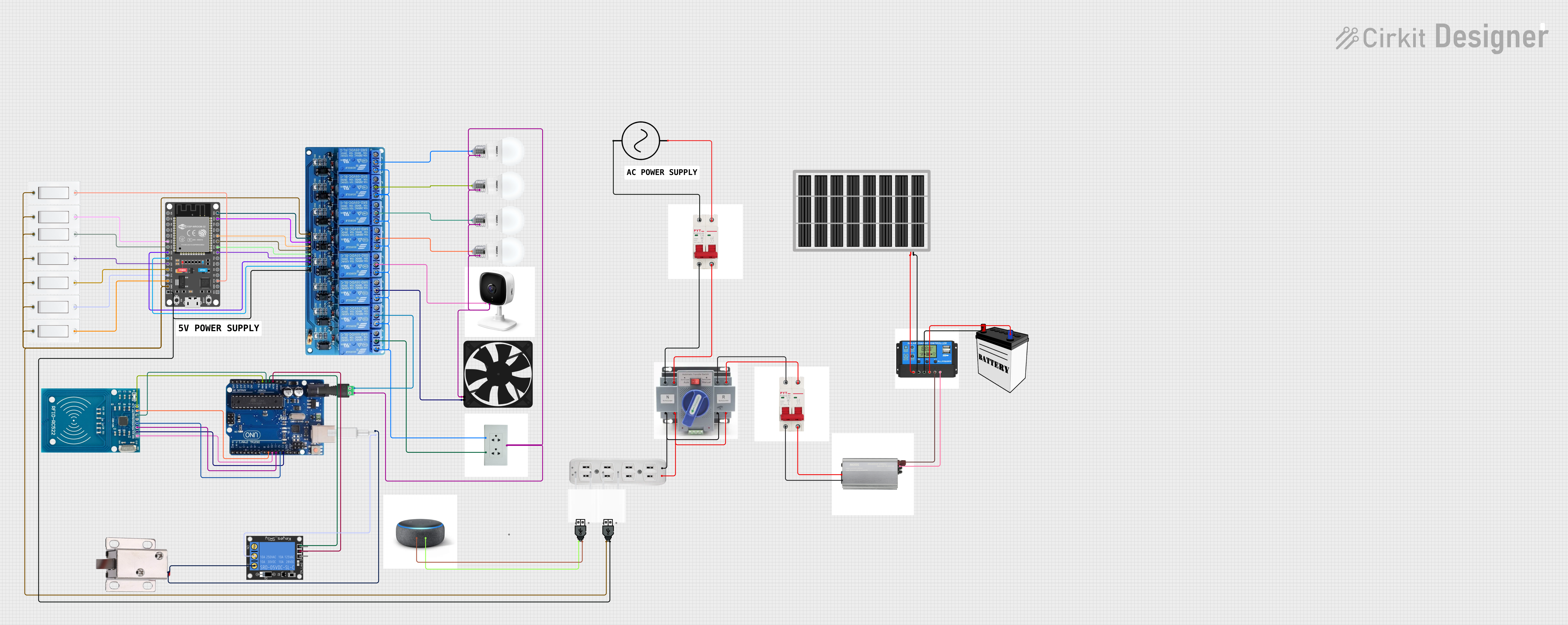
Example: Connecting an ATS to an Arduino UNO
An ATS can be monitored or controlled using an Arduino UNO. Below is an example code snippet to monitor the status of the primary and secondary power sources using digital inputs.
// Pin definitions
const int primarySourcePin = 2;  // Digital pin for primary source status
const int secondarySourcePin = 3; // Digital pin for secondary source status
const int loadStatusPin = 13;    // Built-in LED to indicate load status

void setup() {
  pinMode(primarySourcePin, INPUT);  // Set primary source pin as input
  pinMode(secondarySourcePin, INPUT); // Set secondary source pin as input
  pinMode(loadStatusPin, OUTPUT);    // Set load status pin as output
  Serial.begin(9600);               // Initialize serial communication
}

void loop() {
  // Read the status of the primary and secondary sources
  bool primaryStatus = digitalRead(primarySourcePin);
  bool secondaryStatus = digitalRead(secondarySourcePin);

  // Print the status to the Serial Monitor
  Serial.print("Primary Source: ");
  Serial.println(primaryStatus ? "ON" : "OFF");
  Serial.print("Secondary Source: ");
  Serial.println(secondaryStatus ? "ON" : "OFF");

  // Indicate load status based on power source availability
  if (primaryStatus) {
    digitalWrite(loadStatusPin, HIGH); // Load powered by primary source
  } else if (secondaryStatus) {
    digitalWrite(loadStatusPin, HIGH); // Load powered by secondary source
  } else {
    digitalWrite(loadStatusPin, LOW);  // No power to the load
  }

  delay(1000); // Wait for 1 second before the next update
}
Troubleshooting and FAQs
Common Issues and Solutions
Issue: The ATS does not switch to the secondary source during a power outage.
- Solution: Check the control circuit and ensure the secondary source is operational and properly connected.
Issue: The ATS switches back and forth between sources frequently.
- Solution: Adjust the delay time settings to prevent rapid switching. Verify the stability of both power sources.
Issue: The load does not receive power from either source.
- Solution: Inspect the wiring and ensure the load is properly connected to the Load Output terminal. Check for blown fuses or tripped breakers.
Issue: The ATS generates excessive heat during operation.
- Solution: Verify that the ATS is not overloaded. Ensure proper ventilation and that the ATS is operating within its rated specifications.
FAQs
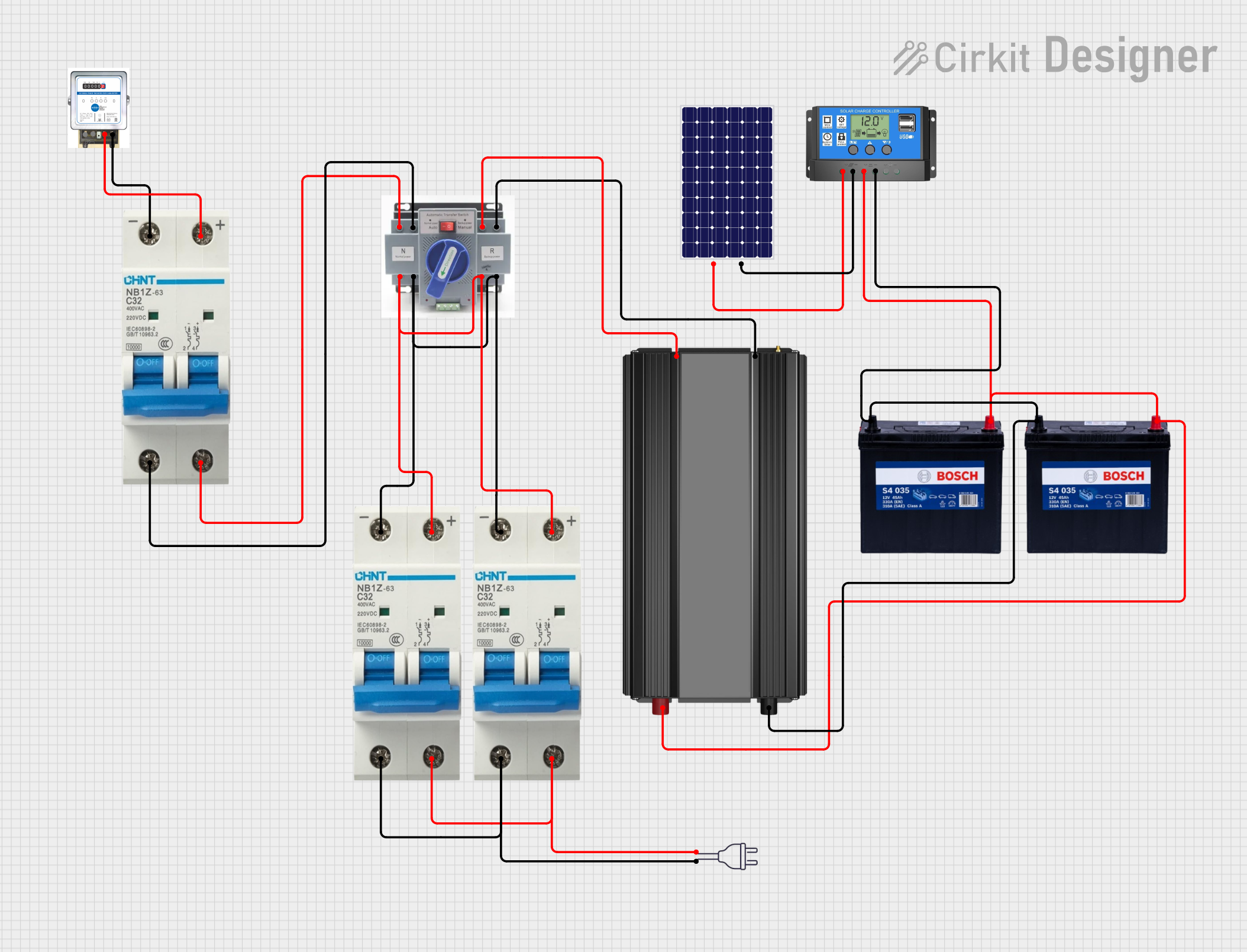
Q: Can I use an ATS with renewable energy sources like solar panels?
A: Yes, but ensure the ATS is compatible with the voltage and current characteristics of the renewable energy source.Q: How often should I maintain my ATS?
A: Perform routine maintenance every 6-12 months, including visual inspections, cleaning, and testing.Q: Can I manually override the ATS?
A: Many ATS models include a manual override feature. Refer to the manufacturer's manual for instructions.Q: Is it safe to install an ATS myself?
A: Installation should be performed by a qualified electrician to ensure safety and compliance with local codes.