How to Use lora rylr 998: Examples, Pinouts, and Specs
Introduction
The LoRa RYLR 998 is a low-power, long-range transceiver module designed for wireless communication using LoRa (Long Range) technology. It operates in the 433MHz, 868MHz, or 915MHz frequency bands, making it ideal for a wide range of IoT applications. This module enables devices to communicate over several kilometers with minimal power consumption, making it a popular choice for remote monitoring, smart agriculture, industrial automation, and smart city projects.
Explore Projects Built with lora rylr 998


Explore Projects Built with lora rylr 998
Common Applications
- Smart Agriculture: Monitoring soil moisture, weather conditions, and crop health.
- Industrial Automation: Wireless control and monitoring of machinery.
- Smart Cities: Applications like parking management, street lighting, and waste management.
- Asset Tracking: Long-range tracking of vehicles, goods, or equipment.
- Environmental Monitoring: Collecting data from remote sensors for air quality, temperature, or humidity.
Technical Specifications
The following table outlines the key technical details of the LoRa RYLR 998 module:
| Parameter | Specification |
|---|---|
| Frequency Bands | 433MHz, 868MHz, 915MHz |
| Modulation Technique | LoRa (Long Range) |
| Communication Range | Up to 10 km (line of sight) |
| Operating Voltage | 2.8V to 3.6V |
| Operating Current | 38mA (transmit), 10.5mA (receive) |
| Sleep Current | < 1 µA |
| Data Rate | 0.3 kbps to 37.5 kbps |
| Interface | UART (3.3V logic level) |
| Antenna Connector | IPEX (U.FL) |
| Operating Temperature | -40°C to +85°C |
| Dimensions | 22mm x 12mm x 3mm |
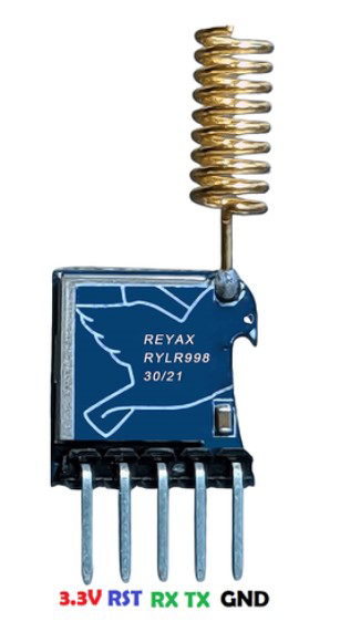
Pin Configuration
The LoRa RYLR 998 module has a simple pinout for easy integration into circuits. Below is the pin configuration:
| Pin Number | Pin Name | Description |
|---|---|---|
| 1 | VCC | Power supply input (2.8V to 3.6V) |
| 2 | GND | Ground |
| 3 | TXD | UART Transmit (3.3V logic level) |
| 4 | RXD | UART Receive (3.3V logic level) |
| 5 | RESET | Module reset (active low) |
| 6 | ANT | Antenna connection (IPEX/U.FL connector) |
Usage Instructions
How to Use the LoRa RYLR 998 in a Circuit
- Power Supply: Connect the VCC pin to a 3.3V power source and the GND pin to ground.
- UART Communication: Connect the TXD pin of the module to the RX pin of your microcontroller and the RXD pin of the module to the TX pin of your microcontroller. Ensure the UART logic levels are 3.3V.
- Antenna: Attach an appropriate antenna to the ANT pin using the IPEX connector for optimal range and performance.
- Reset: Optionally, connect the RESET pin to a GPIO pin of your microcontroller for manual or software-controlled resets.
Important Considerations
- Voltage Levels: Ensure the module operates within the specified voltage range (2.8V to 3.6V). Exceeding this range may damage the module.
- Antenna Placement: Place the antenna in an open area, away from metal objects, to maximize communication range.
- Baud Rate: The default UART baud rate is 9600 bps. Configure your microcontroller to match this baud rate.
- Command Set: The module uses AT commands for configuration and communication. Refer to the module's datasheet for a complete list of supported commands.
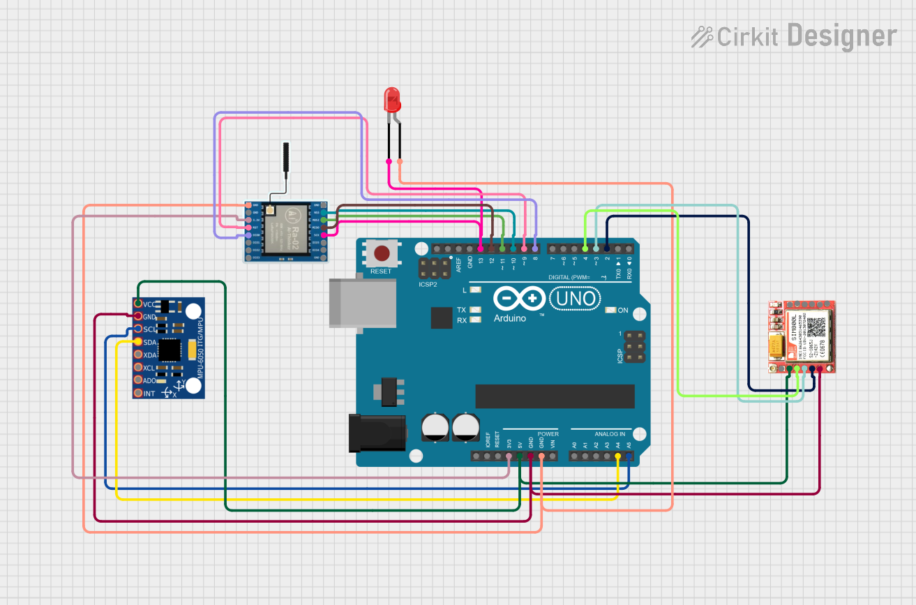
Example: Connecting to an Arduino UNO
Below is an example of how to use the LoRa RYLR 998 with an Arduino UNO. Note that the Arduino UNO operates at 5V logic levels, so a level shifter is required to interface with the 3.3V UART pins of the module.
Circuit Connections
- RYLR 998 VCC → 3.3V power supply
- RYLR 998 GND → Arduino GND
- RYLR 998 TXD → Level shifter → Arduino RX (Pin 0)
- RYLR 998 RXD → Level shifter → Arduino TX (Pin 1)
- RYLR 998 RESET → Arduino GPIO (optional)
Arduino Code Example
#include <SoftwareSerial.h>

// Define RX and TX pins for SoftwareSerial
SoftwareSerial loraSerial(2, 3); // RX = Pin 2, TX = Pin 3

void setup() {
  // Initialize serial communication with the LoRa module
  loraSerial.begin(9600);
  Serial.begin(9600); // For debugging via Serial Monitor

  // Send a test command to the LoRa module
  loraSerial.println("AT"); // Check if the module is responding
  delay(1000);

  // Configure the LoRa module (example: set device address)
  loraSerial.println("AT+ADDRESS=1"); // Set device address to 1
  delay(1000);

  // Set the communication channel
  loraSerial.println("AT+NETWORKID=5"); // Set network ID to 5
  delay(1000);

  // Set the data rate
  loraSerial.println("AT+PARAMETER=10,7,1,4"); // Example parameters
  delay(1000);

  Serial.println("LoRa module configured.");
}

void loop() {
  // Send a message
  loraSerial.println("AT+SEND=1,5,Hello"); // Send "Hello" to device 1
  delay(5000);

  // Check for incoming messages
  if (loraSerial.available()) {
    String message = loraSerial.readString();
    Serial.println("Received: " + message);
  }
}
Notes
- Use a 3.3V regulator if your power source exceeds 3.6V.
- Ensure the antenna is securely connected before powering the module.
Troubleshooting and FAQs
Common Issues and Solutions
No Response to AT Commands
- Ensure the module is powered correctly (check VCC and GND connections).
- Verify the UART connections (TXD and RXD) and ensure the baud rate is set to 9600 bps.
- Check for loose or incorrect wiring.
Poor Communication Range
- Ensure the antenna is properly connected and placed in an open area.
- Avoid obstructions like walls or metal objects between the transmitter and receiver.
Module Not Powering On
- Verify the input voltage is within the specified range (2.8V to 3.6V).
- Check for short circuits or incorrect wiring.
Data Transmission Fails
- Ensure both devices are configured with the same network ID and communication parameters.
- Check for interference from other devices operating in the same frequency band.
FAQs
Q: Can the RYLR 998 module communicate with other LoRa modules?
A: Yes, as long as the frequency, network ID, and communication parameters match.Q: What is the maximum range of the module?
A: The module can achieve up to 10 km range in line-of-sight conditions. Obstacles may reduce the range.Q: Can I use the module with a 5V microcontroller?
A: Yes, but you must use a level shifter to convert the 5V UART signals to 3.3V.Q: How do I reset the module?
A: Pull the RESET pin low for a brief moment (e.g., 100 ms) to reset the module.
This concludes the documentation for the LoRa RYLR 998 module. For further details, refer to the official datasheet or user manual.