How to Use LiDAR TF Mini S: Examples, Pinouts, and Specs
Introduction
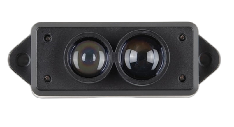
The LiDAR TF Mini S (SEN0259) by Benewake is a compact and versatile Light Detection and Ranging (LiDAR) sensor designed for accurate distance measurement. Utilizing laser light, this sensor can measure distances to objects with high precision, making it an essential component in robotics, drones, and autonomous vehicles for obstacle detection, navigation, and mapping.
Explore Projects Built with LiDAR TF Mini S
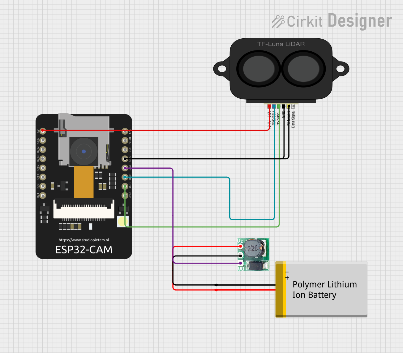
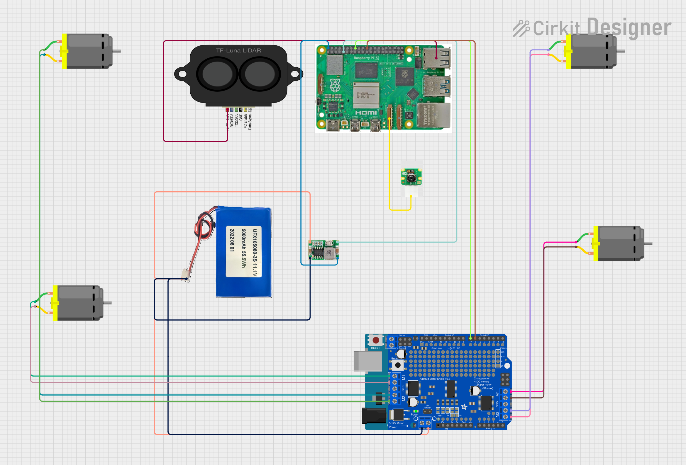
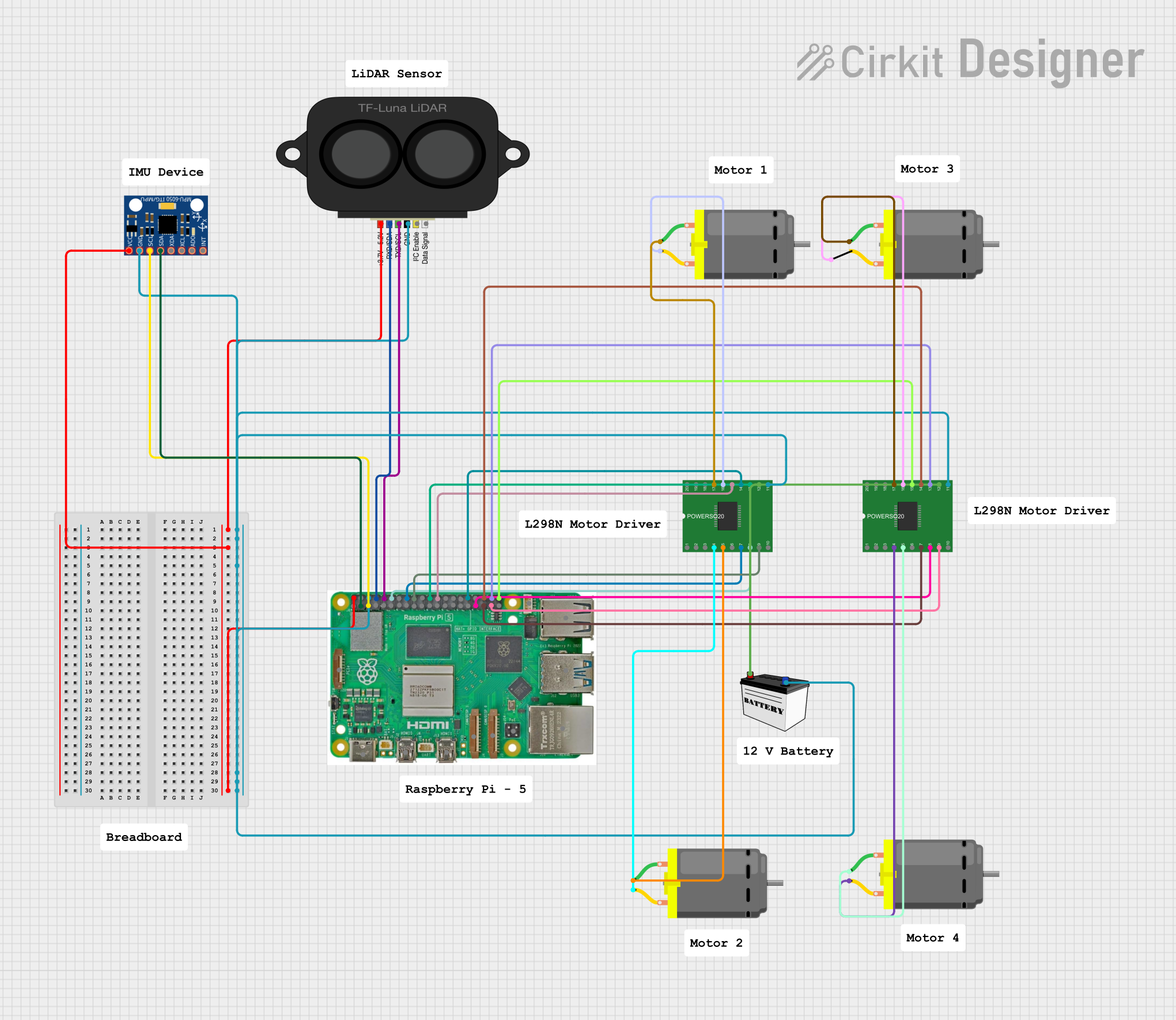
Explore Projects Built with LiDAR TF Mini S
Common Applications and Use Cases
- Robotics: Obstacle avoidance, navigation, and environment scanning.
- Drones: Altitude control, terrain following, and collision avoidance.
- Autonomous vehicles: Distance measurement and environmental mapping.
- Industrial automation: Object detection and distance measurement in manufacturing lines.
Technical Specifications
Key Technical Details
- Operating Range: 0.1 to 12 meters
- Accuracy: ±6cm (in the range of 0.1-6m), ±1% (in the range of 6m-12m)
- Resolution: 1cm
- Frame Rate: Up to 1000Hz
- Wavelength: 850nm
- Operating Voltage: 5V (±0.5V)
- Average Current Consumption: 140mA
- Peak Current Consumption: 200mA
- Interface: UART/I2C
- Operating Temperature: -20°C to 60°C
Pin Configuration and Descriptions
| Pin Number | Name | Description |
|---|---|---|
| 1 | VCC | Power supply (5V) |
| 2 | GND | Ground connection |
| 3 | RX | UART Receive (connect to TX of the controller) |
| 4 | TX | UART Transmit (connect to RX of the controller) |
| 5 | SDA | I2C Data (optional use) |
| 6 | SCL | I2C Clock (optional use) |
Usage Instructions
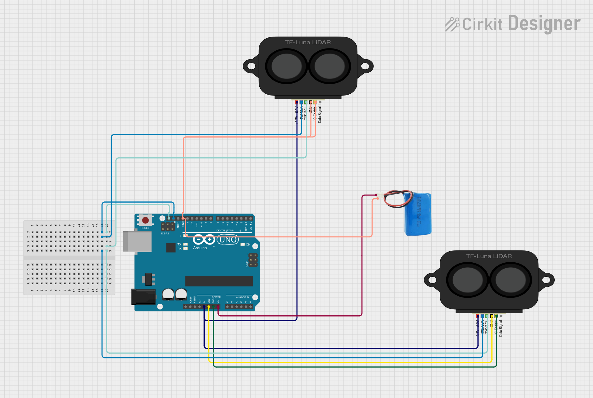
How to Use the Component in a Circuit
- Connect the VCC pin to a 5V power supply.
- Connect the GND pin to the ground of the power supply.
- For UART communication, connect the RX pin to the TX pin of the controller (e.g., Arduino UNO), and the TX pin to the RX pin of the controller.
- For I2C communication, connect the SDA and SCL pins to the corresponding I2C data and clock lines on the controller.
Important Considerations and Best Practices
- Ensure that the power supply is stable and within the specified voltage range.
- Avoid exposing the sensor to direct sunlight or strong reflections to prevent measurement errors.
- Keep the sensor away from dust and moisture to maintain accuracy and longevity.
- Use appropriate level shifters if the controller operates at a different logic level than 5V.
Example Code for Arduino UNO
#include <SoftwareSerial.h>

SoftwareSerial mySerial(10, 11); // RX, TX

void setup() {
  Serial.begin(115200);
  mySerial.begin(115200); // Initialize the connection with the LiDAR
}

void loop() {
  if (mySerial.available()) { // Check if data is available to read
    uint8_t highByte = mySerial.read(); // Read the high byte (distance)
    uint8_t lowByte = mySerial.read(); // Read the low byte (distance)
    uint16_t distance = (highByte << 8) + lowByte; // Calculate the distance
    Serial.print("Distance: ");
    Serial.print(distance);
    Serial.println("cm");
  }
  delay(100); // Wait for a short period before reading again
}
Troubleshooting and FAQs
Common Issues Users Might Face
- Inaccurate Measurements: Ensure there are no obstructions or reflective surfaces near the sensor that could interfere with the laser.
- No Data Output: Check all connections, especially the RX and TX pins, and ensure that the power supply is within the specified range.
- Intermittent Functionality: Verify that the sensor is not exposed to extreme temperatures or environmental conditions outside its operating range.
Solutions and Tips for Troubleshooting
- If you experience inaccurate readings, recalibrate the sensor or adjust its position.
- Ensure that the baud rate of the sensor matches the baud rate set in your controller's code.
- If using I2C, check for correct addressing and ensure that there are pull-up resistors on the SDA and SCL lines.
FAQs
Q: Can the LiDAR TF Mini S be used outdoors? A: Yes, but it should be protected from direct sunlight and harsh weather conditions to maintain accuracy.
Q: What is the maximum baud rate for UART communication? A: The maximum baud rate for the TF Mini S is 115200bps.
Q: How can I change the communication interface from UART to I2C? A: The communication interface can be changed using the Benewake provided software tools or by sending specific commands to the sensor. Refer to the manufacturer's guide for detailed instructions.