How to Use sx1262: Examples, Pinouts, and Specs
Introduction
The SX1262, manufactured by NiceRF, is a high-performance, long-range, low-power LoRa transceiver designed for wireless communication in IoT (Internet of Things) applications. Operating in the sub-GHz frequency range, the SX1262 supports LoRa modulation as well as other modulation schemes such as FSK and OOK. This makes it ideal for robust, long-distance data transmission with minimal power consumption, even in challenging environments.
Explore Projects Built with sx1262


Explore Projects Built with sx1262
Common Applications and Use Cases
- Smart metering (e.g., water, gas, and electricity meters)
- Industrial automation and control
- Environmental monitoring (e.g., weather stations, air quality sensors)
- Asset tracking and fleet management
- Smart agriculture and precision farming
- Home automation and security systems
Technical Specifications
Key Technical Details
| Parameter | Value |
|---|---|
| Manufacturer | NiceRF |
| Part ID | SX1262 |
| Frequency Range | 150 MHz to 960 MHz |
| Modulation Schemes | LoRa, FSK, GFSK, MSK, GMSK, OOK |
| Output Power | Up to +22 dBm |
| Sensitivity | Down to -148 dBm (LoRa, SF12, 125 kHz bandwidth) |
| Supply Voltage | 1.8 V to 3.7 V |
| Current Consumption | 4.6 mA (receive mode), 22 mA (transmit mode at +14 dBm) |
| Data Rate | LoRa: 0.018 kbps to 62.5 kbps; FSK: 1.2 kbps to 300 kbps |
| Operating Temperature | -40°C to +85°C |
| Package Type | QFN 4x4 mm, 24 pins |
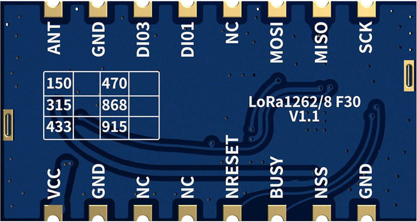
Pin Configuration and Descriptions
The SX1262 has a 24-pin QFN package. Below is the pin configuration and description:
| Pin Number | Pin Name | Description |
|---|---|---|
| 1 | GND | Ground connection |
| 2 | RFIO | RF input/output for antenna connection |
| 3 | VDD | Supply voltage input |
| 4 | DIO1 | Digital I/O pin 1 (configurable interrupt or status output) |
| 5 | DIO2 | Digital I/O pin 2 (configurable interrupt or status output) |
| 6 | DIO3 | Digital I/O pin 3 (configurable interrupt or status output) |
| 7 | BUSY | Busy signal output (indicates ongoing operation) |
| 8 | NRESET | Reset input (active low) |
| 9 | SPI_NSS | SPI chip select (active low) |
| 10 | SPI_SCK | SPI clock input |
| 11 | SPI_MISO | SPI data output (Master In Slave Out) |
| 12 | SPI_MOSI | SPI data input (Master Out Slave In) |
| 13 | GND | Ground connection |
| 14 | VDD | Supply voltage input |
| 15 | RF_SWITCH_CTRL1 | RF switch control signal 1 |
| 16 | RF_SWITCH_CTRL2 | RF switch control signal 2 |
| 17 | XTAL_IN | Crystal oscillator input |
| 18 | XTAL_OUT | Crystal oscillator output |
| 19 | GND | Ground connection |
| 20 | VDD | Supply voltage input |
| 21 | ANT_SW | Antenna switch control |
| 22 | GND | Ground connection |
| 23 | VDD | Supply voltage input |
| 24 | GND | Ground connection |
Usage Instructions
How to Use the SX1262 in a Circuit
- Power Supply: Connect the VDD pins to a stable power supply within the range of 1.8 V to 3.7 V. Ensure proper decoupling capacitors are placed close to the VDD pins to minimize noise.
- Antenna Connection: Connect the RFIO pin to an appropriate antenna through an impedance-matching network for optimal performance.
- SPI Communication: Use the SPI interface (SPI_NSS, SPI_SCK, SPI_MISO, SPI_MOSI) to communicate with the SX1262. Ensure the SPI clock frequency does not exceed the maximum supported by the device.
- Crystal Oscillator: Connect a 32 MHz crystal oscillator to the XTAL_IN and XTAL_OUT pins. Use appropriate load capacitors as specified in the datasheet.
- GPIO Configuration: Configure the DIO pins as needed for interrupts or status signals. These pins can be programmed for various functions such as packet reception, transmission, or error signaling.
- Reset and Busy Signals: Use the NRESET pin to reset the device when required. Monitor the BUSY pin to ensure the device is ready for the next operation.
Important Considerations and Best Practices
- Impedance Matching: Properly design the RF matching network to ensure maximum power transfer between the SX1262 and the antenna.
- Power Management: Use low-dropout regulators (LDOs) or DC-DC converters to provide a clean and stable power supply.
- Thermal Management: Ensure adequate thermal dissipation, especially when operating at high output power levels.
- Firmware Configuration: Use the appropriate LoRa or FSK settings in the firmware to match the application requirements (e.g., frequency, bandwidth, spreading factor).
- Regulatory Compliance: Ensure the design complies with regional RF regulations (e.g., FCC, CE) for the intended frequency band.
Example Code for Arduino UNO
Below is an example of how to interface the SX1262 with an Arduino UNO using the SPI interface:
#include <SPI.h>

// Define SX1262 pin connections
#define NSS_PIN 10    // SPI chip select
#define RESET_PIN 9   // Reset pin
#define BUSY_PIN 8    // Busy pin
#define DIO1_PIN 7    // DIO1 pin

void setup() {
  // Initialize serial communication for debugging
  Serial.begin(9600);

  // Initialize SPI
  SPI.begin();

  // Configure SX1262 control pins
  pinMode(NSS_PIN, OUTPUT);
  pinMode(RESET_PIN, OUTPUT);
  pinMode(BUSY_PIN, INPUT);
  pinMode(DIO1_PIN, INPUT);

  // Reset the SX1262
  digitalWrite(RESET_PIN, LOW);
  delay(10); // Hold reset low for 10 ms
  digitalWrite(RESET_PIN, HIGH);
  delay(10); // Wait for the device to initialize

  Serial.println("SX1262 initialized.");
}

void loop() {
  // Example: Check if the SX1262 is busy
  if (digitalRead(BUSY_PIN) == LOW) {
    Serial.println("SX1262 is ready.");
  } else {
    Serial.println("SX1262 is busy.");
  }

  delay(1000); // Wait 1 second before checking again
}
Troubleshooting and FAQs
Common Issues and Solutions
No Communication with the SX1262
- Cause: Incorrect SPI connections or configuration.
- Solution: Verify the SPI wiring and ensure the SPI clock frequency is within the supported range.
Poor RF Performance
- Cause: Improper antenna matching or interference.
- Solution: Check the impedance-matching network and ensure the antenna is designed for the operating frequency.
Device Not Responding After Reset
- Cause: Insufficient reset timing or power supply issues.
- Solution: Ensure the reset pin is held low for at least 10 ms and verify the power supply stability.
High Power Consumption
- Cause: Incorrect power mode configuration.
- Solution: Use the low-power modes provided by the SX1262 when the device is idle.
FAQs
Can the SX1262 operate in the 2.4 GHz band?
- No, the SX1262 is designed for sub-GHz frequencies (150 MHz to 960 MHz).
What is the maximum range of the SX1262?
- The range depends on factors such as output power, antenna design, and environmental conditions. In ideal conditions, it can achieve several kilometers.
Is the SX1262 compatible with LoRaWAN?
- Yes, the SX1262 supports LoRa modulation and can be used in LoRaWAN networks with appropriate firmware.
Can I use the SX1262 with a 5V microcontroller?
- Yes, but you must use level shifters to interface the 5V logic levels with the SX1262's 3.3V logic levels.