How to Use thermocouple: Examples, Pinouts, and Specs
Introduction
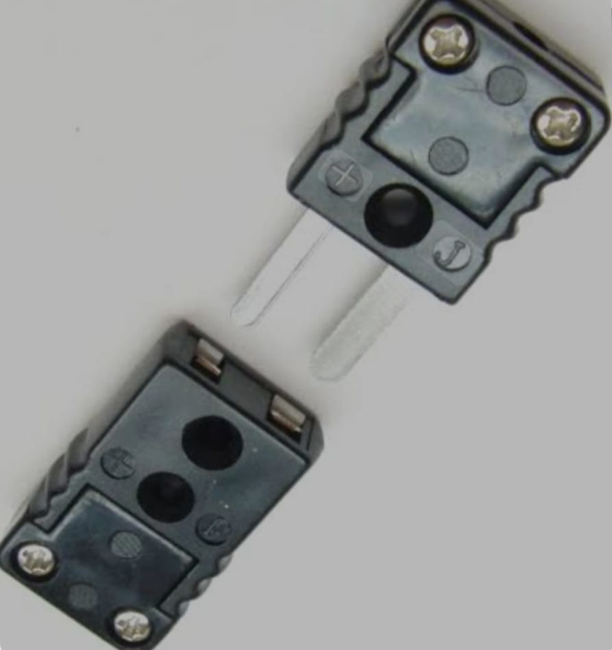
A thermocouple is a sensor used to measure temperature. It consists of two different types of metals joined at one end, which produce a voltage proportional to the temperature difference between the joined end and the other ends. Thermocouples are widely used due to their wide temperature range, durability, and relatively low cost.
Explore Projects Built with thermocouple

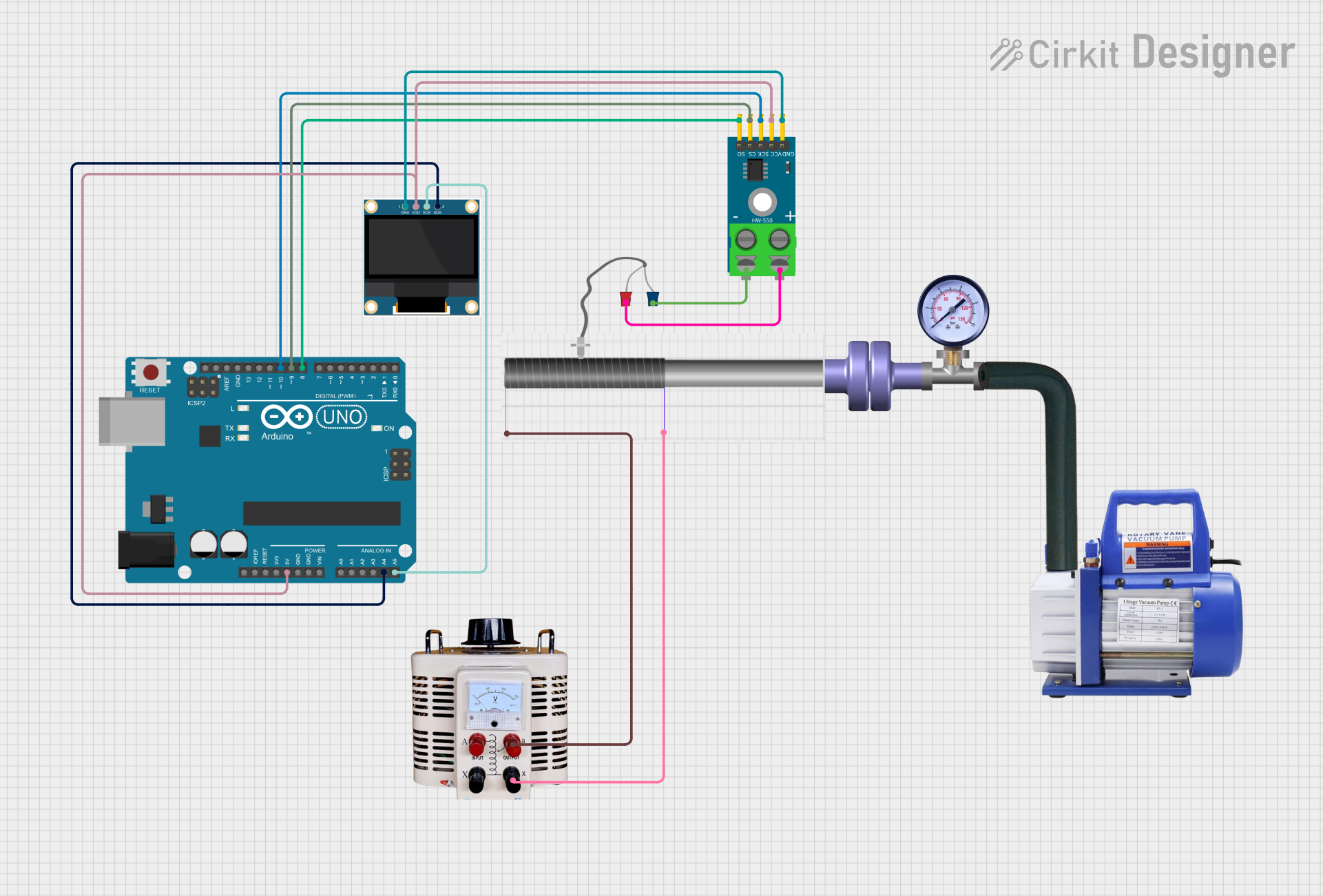
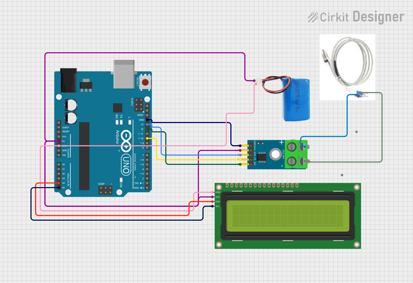
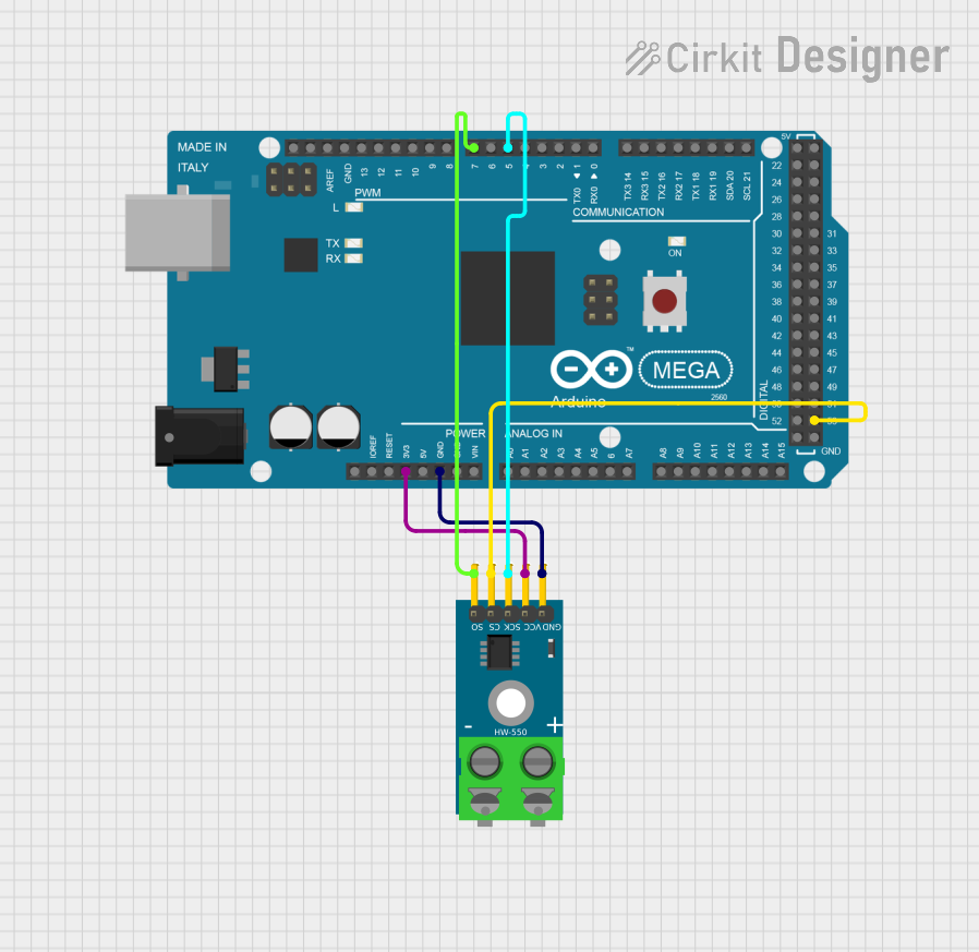
Explore Projects Built with thermocouple
Common Applications and Use Cases
- Industrial temperature monitoring
- HVAC systems
- Home appliances (e.g., ovens, water heaters)
- Scientific research
- Automotive sensors
Technical Specifications
Key Technical Details
| Parameter | Value |
|---|---|
| Temperature Range | -200°C to 1350°C (Type K) |
| Voltage Output | 0 to 54.886 mV (Type K) |
| Accuracy | ±1.5°C or ±0.4% (Type K) |
| Response Time | Typically 0.5 to 5 seconds |
| Insulation | Ceramic, fiberglass, or metal |
| Wire Material | Chromel and Alumel (Type K) |
Pin Configuration and Descriptions
| Pin Number | Pin Name | Description |
|---|---|---|
| 1 | Positive | Chromel (Nickel-Chromium alloy) |
| 2 | Negative | Alumel (Nickel-Aluminum alloy) |
Usage Instructions
How to Use the Component in a Circuit
Connect the Thermocouple:
- Connect the positive pin (Chromel) to the positive input of your measurement device.
- Connect the negative pin (Alumel) to the negative input of your measurement device.
Amplify the Signal:
- Thermocouples produce a very small voltage, so an amplifier (e.g., MAX6675 or MAX31855) is often used to boost the signal to a readable level.
Read the Temperature:
- Use a microcontroller (e.g., Arduino UNO) to read the amplified signal and convert it to a temperature value.
Important Considerations and Best Practices
- Cold Junction Compensation: Thermocouples measure the temperature difference between the junction and the reference point. Ensure proper cold junction compensation for accurate readings.
- Calibration: Regularly calibrate your thermocouple to maintain accuracy.
- Shielding: Use shielded cables to minimize electrical noise interference.
- Proper Installation: Ensure the thermocouple is properly installed in the measurement environment to avoid errors.
Example Code for Arduino UNO
#include <SPI.h>
#include "Adafruit_MAX31855.h"

// Define the pins for the thermocouple amplifier
#define DO   3
#define CS   4
#define CLK  5

// Create an instance of the MAX31855 thermocouple amplifier
Adafruit_MAX31855 thermocouple(CLK, CS, DO);

void setup() {
  Serial.begin(9600);
  // Wait for serial port to connect. Needed for native USB port only
  while (!Serial) {
    delay(1);
  }
  Serial.println("MAX31855 test");
}

void loop() {
  // Read the temperature in Celsius
  double celsius = thermocouple.readCelsius();
  if (isnan(celsius)) {
    Serial.println("Something went wrong with the thermocouple!");
  } else {
    Serial.print("C = ");
    Serial.println(celsius);
  }

  // Read the temperature in Fahrenheit
  double fahrenheit = thermocouple.readFahrenheit();
  if (isnan(fahrenheit)) {
    Serial.println("Something went wrong with the thermocouple!");
  } else {
    Serial.print("F = ");
    Serial.println(fahrenheit);
  }

  delay(1000); // Wait for 1 second before reading again
}
Troubleshooting and FAQs
Common Issues Users Might Face
Inaccurate Readings:
- Solution: Ensure proper cold junction compensation and calibration. Check for any loose connections or damaged wires.
No Output Signal:
- Solution: Verify the connections and ensure the amplifier is powered correctly. Check for any short circuits.
Fluctuating Readings:
- Solution: Use shielded cables to minimize electrical noise. Ensure the thermocouple is properly installed and not exposed to rapid temperature changes.
FAQs
Q: Can I use a thermocouple without an amplifier? A: While it is possible, the voltage output from a thermocouple is very small and difficult to read accurately without amplification.
Q: How often should I calibrate my thermocouple? A: Calibration frequency depends on the application and usage conditions. For critical applications, calibrate regularly (e.g., monthly or quarterly).
Q: What type of thermocouple should I use? A: The type of thermocouple depends on the temperature range and environment. Type K is common for general-purpose use, but other types (e.g., J, T, E) may be more suitable for specific applications.
This documentation provides a comprehensive guide to understanding, using, and troubleshooting thermocouples. Whether you are a beginner or an experienced user, following these guidelines will help you achieve accurate and reliable temperature measurements.