How to Use FS: Examples, Pinouts, and Specs
Introduction
A fuse (FS) is a critical safety device used in electrical circuits to protect against overcurrent conditions. When the current flowing through the circuit exceeds a predetermined level, the fuse "blows" or breaks the connection, thereby preventing potential damage to the circuit components and reducing the risk of fire. Fuses are widely used in various applications, including household appliances, automotive systems, industrial machinery, and electronic devices.
Explore Projects Built with FS
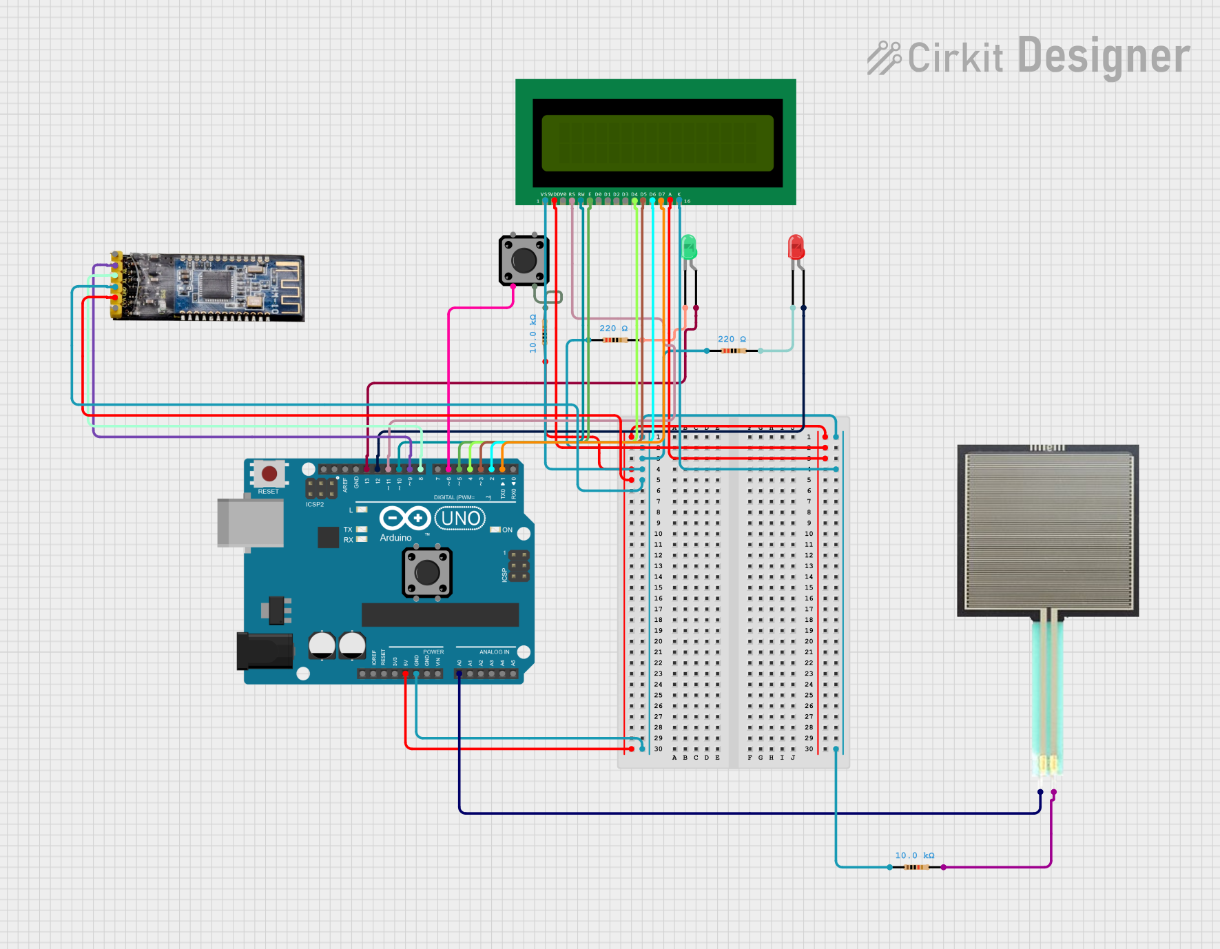
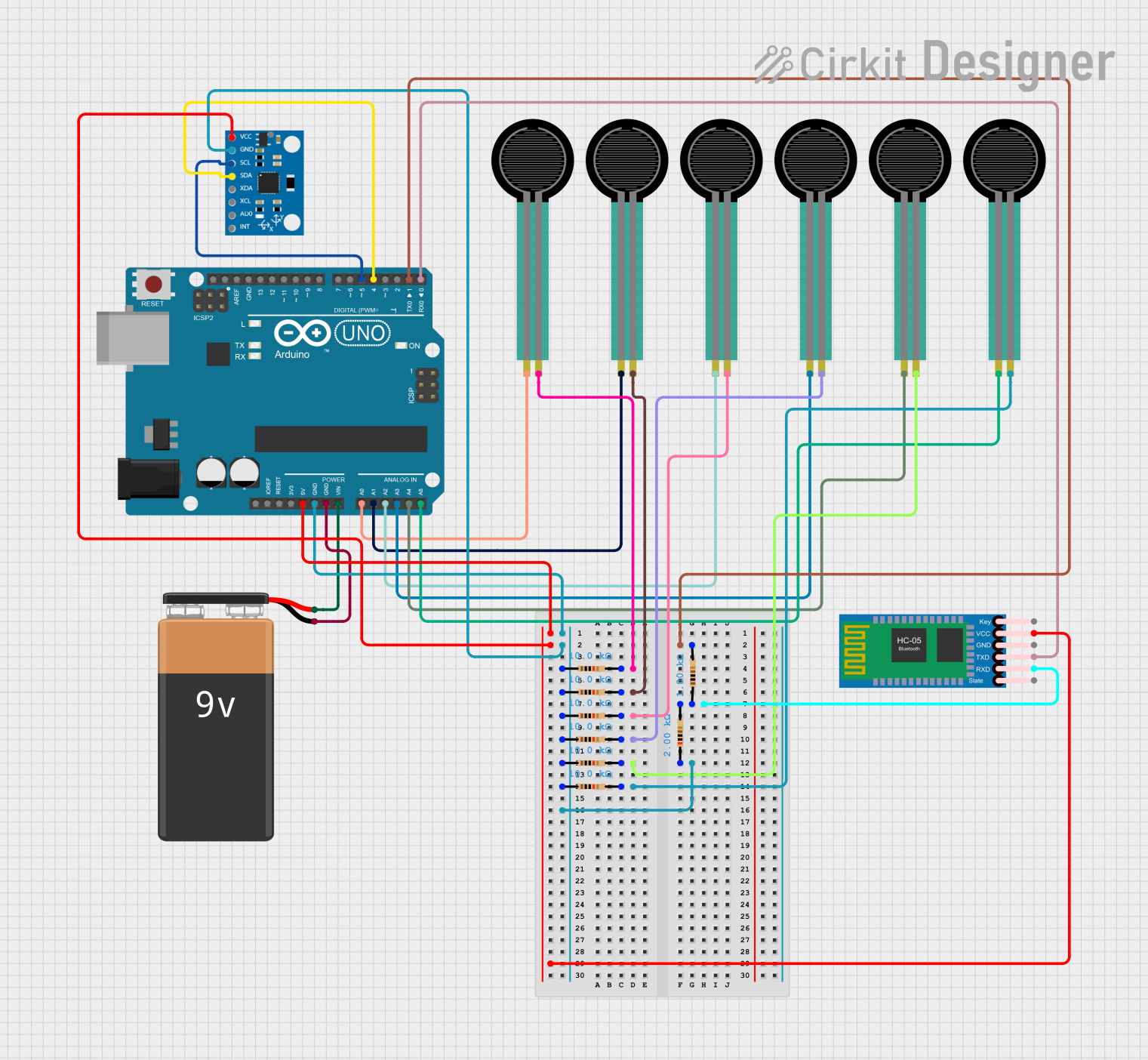

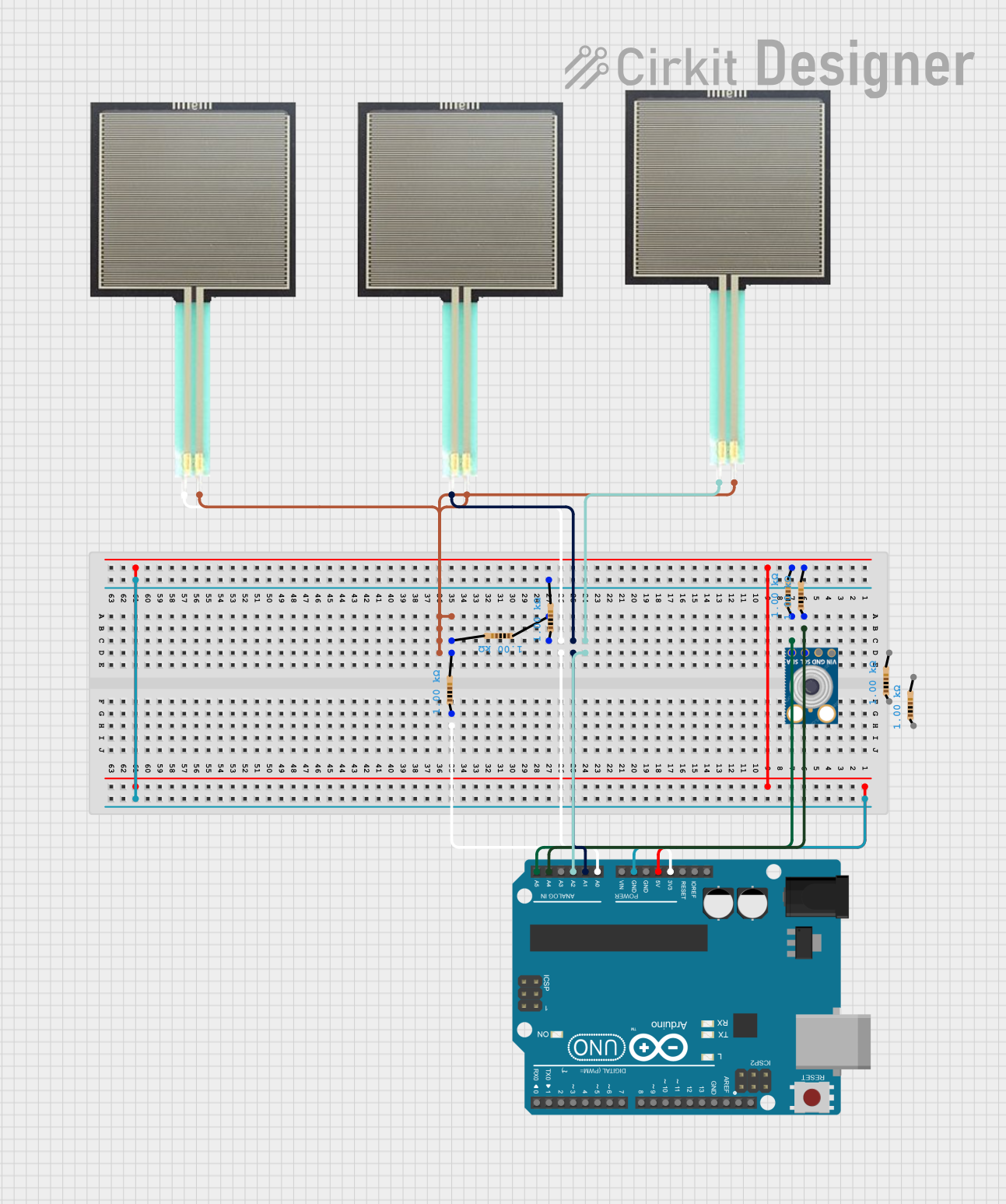
Explore Projects Built with FS
Technical Specifications
Key Technical Details
| Parameter | Value/Description |
|---|---|
| Rated Voltage | 250V AC/DC |
| Rated Current | 0.5A to 30A (varies by fuse type) |
| Breaking Capacity | 35A to 10kA (varies by fuse type) |
| Response Time | Fast-acting or slow-blow (time-delay) |
| Material | Ceramic, glass, or plastic housing |
| Mounting Type | Through-hole, surface mount, or cartridge |
Pin Configuration and Descriptions
| Pin Number | Description |
|---|---|
| 1 | Input terminal (connects to the power source) |
| 2 | Output terminal (connects to the load) |
Usage Instructions
How to Use the Fuse in a Circuit
Identify the Appropriate Fuse: Select a fuse with the correct rated current and voltage for your application. Ensure the breaking capacity is suitable for the potential fault current.
Mounting the Fuse: Depending on the type of fuse, mount it appropriately:
- Through-hole: Insert the fuse into the designated holes on the PCB and solder it in place.
- Surface mount: Place the fuse on the PCB pads and solder it using reflow soldering.
- Cartridge: Insert the fuse into a fuse holder or clip.
Connecting the Fuse: Connect the input terminal (Pin 1) to the power source and the output terminal (Pin 2) to the load. Ensure secure and reliable connections to prevent loose contacts.
Testing the Circuit: Power on the circuit and verify that the fuse is functioning correctly. If the fuse blows, check for overcurrent conditions and rectify the issue before replacing the fuse.
Important Considerations and Best Practices
- Correct Rating: Always use a fuse with the correct current and voltage rating for your application to ensure proper protection.
- Type of Fuse: Choose between fast-acting and slow-blow fuses based on the nature of the load. Fast-acting fuses are suitable for sensitive electronics, while slow-blow fuses are better for inductive loads.
- Replacement: When replacing a blown fuse, use an identical fuse to maintain the same level of protection.
- Inspection: Regularly inspect fuses for signs of wear or damage and replace them as needed.
Troubleshooting and FAQs
Common Issues Users Might Face
Fuse Blows Frequently:
- Cause: Overcurrent condition or incorrect fuse rating.
- Solution: Check the circuit for faults and ensure the fuse rating matches the application requirements.
Fuse Does Not Blow During Overcurrent:
- Cause: Incorrect fuse rating or faulty fuse.
- Solution: Verify the fuse rating and replace the fuse if necessary.
Fuse Holder/Clip Issues:
- Cause: Loose or corroded connections.
- Solution: Ensure secure and clean connections in the fuse holder or clip.
Solutions and Tips for Troubleshooting
- Check Connections: Ensure all connections are secure and free from corrosion.
- Verify Ratings: Double-check the fuse ratings to ensure they match the circuit requirements.
- Inspect Circuit: Look for potential short circuits or overcurrent conditions that may cause the fuse to blow.
- Use Quality Components: Use high-quality fuses and holders to ensure reliable protection.
Example Code for Arduino UNO
If you are using a fuse in a circuit connected to an Arduino UNO, here is an example code to monitor the status of the fuse:
const int fusePin = 2; // Pin connected to the fuse status indicator

void setup() {
  pinMode(fusePin, INPUT); // Set fusePin as input
  Serial.begin(9600); // Initialize serial communication
}

void loop() {
  int fuseStatus = digitalRead(fusePin); // Read the status of the fuse

  if (fuseStatus == HIGH) {
    Serial.println("Fuse is intact."); // Print message if fuse is intact
  } else {
    Serial.println("Fuse is blown!"); // Print message if fuse is blown
  }

  delay(1000); // Wait for 1 second before checking again
}
In this example, the fusePin is connected to a digital input pin on the Arduino UNO. The code continuously monitors the status of the fuse and prints a message to the serial monitor indicating whether the fuse is intact or blown.
By following this documentation, users can effectively utilize fuses in their electrical circuits, ensuring safety and protection against overcurrent conditions.