How to Use POWERSUP: Examples, Pinouts, and Specs

 Design with POWERSUP in Cirkit Designer
Introduction
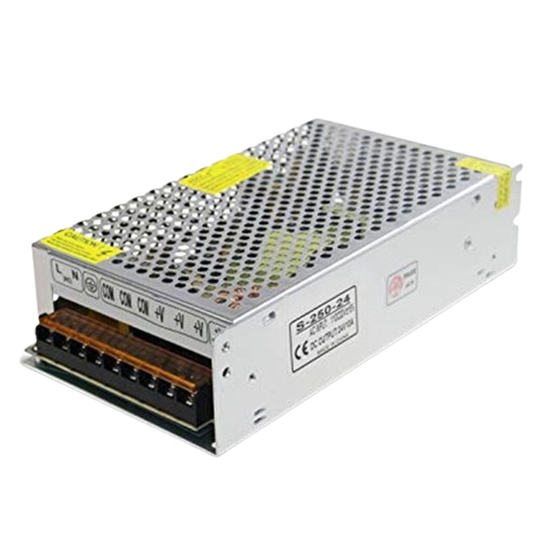
The POWERSUP is a versatile power supply unit (PSU) designed to provide electrical power to various electrical loads. It efficiently converts electrical energy from a source to the correct voltage, current, and frequency required to power the load. This component is essential in numerous applications, including powering electronic circuits, devices, and systems in both hobbyist and professional projects.
Explore Projects Built with POWERSUP

 Open Project in Cirkit Designer
 Open Project in Cirkit Designer
 Open Project in Cirkit Designer
 Open Project in Cirkit Designer
Explore Projects Built with POWERSUP

 Open Project in Cirkit Designer
 Open Project in Cirkit Designer
 Open Project in Cirkit Designer
 Open Project in Cirkit Designer
Common Applications and Use Cases
- Arduino Projects: Providing stable power to Arduino boards and connected components.
- Embedded Systems: Supplying power to microcontrollers and peripheral devices.
- Prototyping: Powering breadboards and development boards during the design phase.
- Consumer Electronics: Used in devices like computers, televisions, and gaming consoles.
- Industrial Equipment: Powering machinery and control systems in industrial settings.
Technical Specifications
Key Technical Details
| Parameter | Value |
|---|---|
| Input Voltage | 100-240V AC |
| Output Voltage | 5V, 12V, 24V DC (selectable) |
| Output Current | Up to 5A |
| Power Rating | 60W |
| Frequency | 50/60 Hz |
| Efficiency | >85% |
| Operating Temperature | -10°C to 50°C |
| Dimensions | 100mm x 50mm x 30mm |
| Weight | 150g |
Pin Configuration and Descriptions
| Pin No. | Name | Description |
|---|---|---|
| 1 | AC_L | AC Live input (100-240V AC) |
| 2 | AC_N | AC Neutral input (100-240V AC) |
| 3 | GND | Ground |
| 4 | V_OUT+ | Positive DC output (5V, 12V, 24V selectable) |
| 5 | V_OUT- | Negative DC output (Ground) |
| 6 | ADJ | Output voltage adjustment (fine-tuning) |
Usage Instructions
How to Use the POWERSUP in a Circuit
Connect the AC Input:
- Connect the AC_L pin to the live wire of the AC source.
- Connect the AC_N pin to the neutral wire of the AC source.
Connect the DC Output:
- Connect the V_OUT+ pin to the positive terminal of your load.
- Connect the V_OUT- pin to the ground terminal of your load.
Adjust the Output Voltage:
- Use the ADJ pin to fine-tune the output voltage if necessary. This can be done using a small screwdriver to turn the adjustment screw.
Power On:
- Ensure all connections are secure and power on the AC source. The POWERSUP will convert the AC input to the desired DC output.
Important Considerations and Best Practices
- Safety First: Always ensure the power supply is disconnected from the AC source before making any connections or adjustments.
- Heat Dissipation: Ensure adequate ventilation around the PSU to prevent overheating.
- Load Matching: Verify that the load does not exceed the maximum current rating of the PSU.
- Voltage Selection: Double-check the output voltage setting before connecting sensitive electronic components.
Troubleshooting and FAQs
Common Issues and Solutions
No Output Voltage:
- Check Connections: Ensure all input and output connections are secure.
- Verify AC Source: Confirm that the AC source is providing power.
- Fuse Check: Inspect the internal fuse and replace if blown.
Overheating:
- Ventilation: Ensure the PSU has adequate ventilation.
- Load Check: Verify that the load does not exceed the PSU's power rating.
Fluctuating Output Voltage:
- Adjust Voltage: Use the ADJ pin to stabilize the output voltage.
- Check Load: Ensure the load is stable and not causing fluctuations.
FAQs
Q: Can I use the POWERSUP with an Arduino UNO? A: Yes, the POWERSUP can be used to provide stable power to an Arduino UNO. Connect the V_OUT+ to the 5V or VIN pin (depending on the output voltage) and V_OUT- to the GND pin of the Arduino.
Q: How do I select the output voltage? A: The output voltage can be selected using a switch or jumper on the PSU. Refer to the specific model's manual for detailed instructions.
Q: What should I do if the PSU is not working after a power surge? A: Check the internal fuse and replace it if necessary. Also, inspect the PSU for any visible damage and test the AC source.
Example Code for Arduino UNO
// Example code to power an Arduino UNO using the POWERSUP
// Connect V_OUT+ to the 5V pin and V_OUT- to the GND pin of the Arduino

void setup() {
  // Initialize serial communication for debugging
  Serial.begin(9600);
  Serial.println("Arduino powered by POWERSUP");
}

void loop() {
  // Your main code here
  Serial.println("Running...");
  delay(1000); // Wait for 1 second
}
This documentation provides a comprehensive guide to using the POWERSUP power supply unit, ensuring both beginners and experienced users can effectively integrate it into their projects.