Cirkit Designer Logo
Cirkit Designer
Your all-in-one circuit design IDE
Home / 
Component Documentation

How to Use Logic Level Shifter Converter Module: Examples, Pinouts, and Specs

Image of Logic Level Shifter Converter Module
Cirkit Designer LogoDesign with Logic Level Shifter Converter Module in Cirkit Designer

Introduction

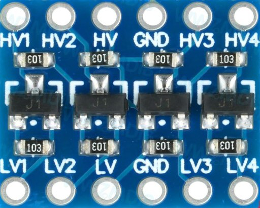
The Logic Level Shifter Converter Module is a versatile electronic component designed to facilitate communication between devices operating at different voltage levels. It is commonly used in circuits where components with varying logic levels, such as 3.3V and 5V, need to interface seamlessly. This module ensures safe and reliable voltage translation, preventing potential damage to sensitive components.

Explore Projects Built with Logic Level Shifter Converter Module

Use Cirkit Designer to design, explore, and prototype these projects online. Some projects support real-time simulation. Click "Open Project" to start designing instantly!
ESP32 and Logic Level Converter-Based Wi-Fi Controlled Interface
Image of Toshiba AC ESP32 devkit v1: A project utilizing Logic Level Shifter Converter Module in a practical application
This circuit features an ESP32 Devkit V1 microcontroller connected to a Bi-Directional Logic Level Converter, which facilitates voltage level shifting between the ESP32 and external components. The ESP32 is powered through its VIN pin via an alligator clip cable, and the logic level converter is connected to various pins on the ESP32 to manage different voltage levels for communication.
Cirkit Designer LogoOpen Project in Cirkit Designer
Wi-Fi Controlled Device Interface with Wemos D1 Mini and Logic Level Converter
Image of Toshiba AC D1 mini: A project utilizing Logic Level Shifter Converter Module in a practical application
This circuit features a Wemos D1 Mini microcontroller interfaced with a Bi-Directional Logic Level Converter to facilitate communication with a 5V RX/TX module. The level converter ensures proper voltage translation between the 3.3V logic of the Wemos D1 Mini and the 5V logic of the RX/TX module.
Cirkit Designer LogoOpen Project in Cirkit Designer
DC-DC Converter and Relay Module Power Distribution System
Image of relay: A project utilizing Logic Level Shifter Converter Module in a practical application
This circuit consists of a DC-DC converter powering a 6-channel power module, which in turn supplies 5V to a 2-relay module. The power module distributes the converted voltage to the relay module, enabling it to control external devices.
Cirkit Designer LogoOpen Project in Cirkit Designer
Cellular-Enabled IoT Device with Real-Time Clock and Power Management
Image of LRCM PHASE 2 BASIC: A project utilizing Logic Level Shifter Converter Module in a practical application
This circuit features a LilyGo-SIM7000G module for cellular communication and GPS functionality, interfaced with an RTC DS3231 for real-time clock capabilities. It includes voltage sensing through two voltage sensor modules, and uses an 8-channel opto-coupler for isolating different parts of the circuit. Power management is handled by a buck converter connected to a DC power source and batteries, with a fuse for protection and a rocker switch for on/off control. Additionally, there's an LED for indication purposes.
Cirkit Designer LogoOpen Project in Cirkit Designer

Explore Projects Built with Logic Level Shifter Converter Module

Use Cirkit Designer to design, explore, and prototype these projects online. Some projects support real-time simulation. Click "Open Project" to start designing instantly!
Image of Toshiba AC ESP32 devkit v1: A project utilizing Logic Level Shifter Converter Module in a practical application
ESP32 and Logic Level Converter-Based Wi-Fi Controlled Interface
This circuit features an ESP32 Devkit V1 microcontroller connected to a Bi-Directional Logic Level Converter, which facilitates voltage level shifting between the ESP32 and external components. The ESP32 is powered through its VIN pin via an alligator clip cable, and the logic level converter is connected to various pins on the ESP32 to manage different voltage levels for communication.
Cirkit Designer LogoOpen Project in Cirkit Designer
Image of Toshiba AC D1 mini: A project utilizing Logic Level Shifter Converter Module in a practical application
Wi-Fi Controlled Device Interface with Wemos D1 Mini and Logic Level Converter
This circuit features a Wemos D1 Mini microcontroller interfaced with a Bi-Directional Logic Level Converter to facilitate communication with a 5V RX/TX module. The level converter ensures proper voltage translation between the 3.3V logic of the Wemos D1 Mini and the 5V logic of the RX/TX module.
Cirkit Designer LogoOpen Project in Cirkit Designer
Image of relay: A project utilizing Logic Level Shifter Converter Module in a practical application
DC-DC Converter and Relay Module Power Distribution System
This circuit consists of a DC-DC converter powering a 6-channel power module, which in turn supplies 5V to a 2-relay module. The power module distributes the converted voltage to the relay module, enabling it to control external devices.
Cirkit Designer LogoOpen Project in Cirkit Designer
Image of LRCM PHASE 2 BASIC: A project utilizing Logic Level Shifter Converter Module in a practical application
Cellular-Enabled IoT Device with Real-Time Clock and Power Management
This circuit features a LilyGo-SIM7000G module for cellular communication and GPS functionality, interfaced with an RTC DS3231 for real-time clock capabilities. It includes voltage sensing through two voltage sensor modules, and uses an 8-channel opto-coupler for isolating different parts of the circuit. Power management is handled by a buck converter connected to a DC power source and batteries, with a fuse for protection and a rocker switch for on/off control. Additionally, there's an LED for indication purposes.
Cirkit Designer LogoOpen Project in Cirkit Designer

Common Applications and Use Cases

  • Interfacing 3.3V microcontrollers (e.g., ESP8266, ESP32) with 5V peripherals (e.g., sensors, displays).
  • Enabling communication between 1.8V, 3.3V, and 5V logic systems.
  • Bidirectional data transfer in I2C, SPI, UART, and GPIO applications.
  • Protecting low-voltage devices from overvoltage damage.

Technical Specifications

  • Voltage Levels Supported: 1.8V, 3.3V, 5V
  • Number of Channels: Typically 4 bidirectional channels
  • Input Voltage (High Side): 3.3V to 5V
  • Input Voltage (Low Side): 1.8V to 3.3V
  • Maximum Data Rate: Up to 100 kHz (I2C) or higher for other protocols
  • Operating Temperature: -40°C to 85°C
  • Dimensions: Varies by module, typically compact (e.g., 15mm x 20mm)

Pin Configuration and Descriptions

Pin Name Description
HV High voltage input (e.g., 5V). Powers the high-voltage side of the module.
LV Low voltage input (e.g., 3.3V). Powers the low-voltage side of the module.
GND Ground connection. Common ground for both high and low voltage systems.
TX1, TX2, TX3, TX4 High-voltage side data pins for bidirectional communication.
RX1, RX2, RX3, RX4 Low-voltage side data pins for bidirectional communication.

Usage Instructions

How to Use the Component in a Circuit

  1. Power the Module:

    • Connect the HV pin to the high-voltage logic level (e.g., 5V).
    • Connect the LV pin to the low-voltage logic level (e.g., 3.3V).
    • Connect the GND pin to the ground of your circuit.
  2. Connect Data Lines:

    • For each channel, connect the high-voltage side (e.g., TX1) to the high-voltage device.
    • Connect the corresponding low-voltage side (e.g., RX1) to the low-voltage device.
  3. Verify Connections:

    • Ensure that the voltage levels on the HV and LV pins match the operating voltages of the connected devices.
    • Double-check the ground connection to avoid communication issues.
  4. Test the Circuit:

    • Power on the circuit and test communication between the devices. The module will automatically handle bidirectional voltage translation.

Important Considerations and Best Practices

  • Power Supply: Ensure that the HV and LV pins are powered with stable and appropriate voltage levels.
  • Data Rate: For high-speed communication protocols, verify that the module supports the required data rate.
  • Channel Usage: Use the correct channel pairs (e.g., TX1 ↔ RX1) for proper operation.
  • Common Ground: Always connect the ground of the module to the ground of all devices in the circuit.

Example: Connecting to an Arduino UNO

The following example demonstrates how to use the Logic Level Shifter Converter Module to interface a 3.3V sensor with a 5V Arduino UNO.

Circuit Connections

  • HV: Connect to the Arduino's 5V pin.
  • LV: Connect to the sensor's 3.3V pin.
  • GND: Connect to the common ground of the Arduino and the sensor.
  • TX1: Connect to the Arduino's digital pin (e.g., D2).
  • RX1: Connect to the sensor's data pin.

Arduino Code Example

// Example code for reading data from a 3.3V sensor using a logic level shifter
// Ensure the sensor is connected to the RX1 pin of the level shifter module

const int sensorPin = 2; // Arduino pin connected to TX1 of the level shifter

void setup() {
  Serial.begin(9600); // Initialize serial communication
  pinMode(sensorPin, INPUT); // Set the sensor pin as input
}

void loop() {
  int sensorValue = digitalRead(sensorPin); // Read the sensor value
  Serial.println(sensorValue); // Print the sensor value to the Serial Monitor
  delay(500); // Wait for 500ms before the next reading
}

Troubleshooting and FAQs

Common Issues and Solutions

  1. No Communication Between Devices:

    • Cause: Incorrect voltage levels on HV or LV pins.
    • Solution: Verify that the HV and LV pins are powered with the correct voltages.
  2. Data Corruption or Loss:

    • Cause: High data rate exceeding the module's capability.
    • Solution: Reduce the communication speed or use a module rated for higher speeds.
  3. Module Overheating:

    • Cause: Excessive current draw or incorrect wiring.
    • Solution: Check the wiring and ensure the module is not overloaded.
  4. Unstable Operation:

    • Cause: Missing or poor ground connection.
    • Solution: Ensure a solid ground connection between all devices.

FAQs

  • Q: Can this module handle analog signals?
    A: No, the module is designed for digital signals only. Use a dedicated level shifter for analog signals.

  • Q: How many channels can I use simultaneously?
    A: Most modules support 4 bidirectional channels, but check your specific module's datasheet.

  • Q: Can I use this module with I2C communication?
    A: Yes, the module supports bidirectional I2C communication. Connect the SDA and SCL lines to separate channels.

  • Q: Is it safe to connect 1.8V devices to this module?
    A: Yes, as long as the LV pin is powered with 1.8V, the module can safely interface with 1.8V devices.