
How to Use USB_MICROB_PLUG: Examples, Pinouts, and Specs
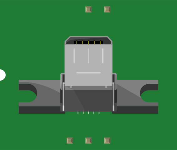
 Design with USB_MICROB_PLUG in Cirkit Designer
Introduction
The USB Micro-B Plug is a small, versatile connector widely used for data transfer and charging in various electronic devices. Its compact design makes it ideal for portable devices such as smartphones, tablets, power banks, and other consumer electronics. The USB Micro-B Plug is part of the USB 2.0 standard and supports high-speed data transfer rates of up to 480 Mbps, as well as power delivery for charging applications.
Explore Projects Built with USB_MICROB_PLUG
 Open Project in Cirkit Designer
 Open Project in Cirkit Designer
 Open Project in Cirkit Designer
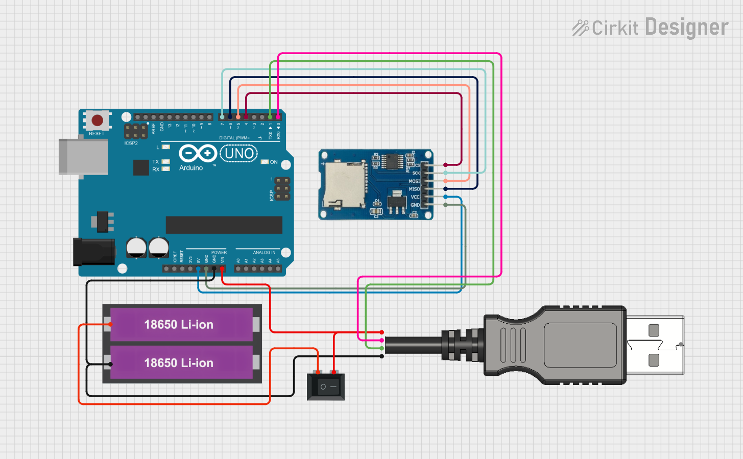 Open Project in Cirkit Designer
Explore Projects Built with USB_MICROB_PLUG
Open Project in Cirkit DesignerOpen Project in Cirkit DesignerOpen Project in Cirkit DesignerOpen Project in Cirkit DesignerCommon Applications and Use Cases
- Charging portable devices such as smartphones, tablets, and cameras
- Data transfer between devices and computers
- Embedded systems and microcontroller projects
- Powering small electronic devices
- USB-based communication in DIY electronics projects
Technical Specifications
The USB Micro-B Plug adheres to the USB 2.0 standard and features a compact 5-pin design. Below are the key technical details:
Key Technical Details
- Standard: USB 2.0
- Data Transfer Rate: Up to 480 Mbps
- Voltage Rating: 5V DC
- Current Rating: Up to 1.8A (depending on cable and device)
- Connector Type: Male, Micro-B
- Durability: Rated for 10,000 connection cycles
- Operating Temperature: -20°C to 60°C
Pin Configuration and Descriptions
The USB Micro-B Plug has five pins, each serving a specific purpose. The table below outlines the pin configuration:
| Pin Number | Name | Description |
|---|---|---|
| 1 | VBUS | Power supply (5V DC) |
| 2 | D- | Data line (negative) for differential signaling |
| 3 | D+ | Data line (positive) for differential signaling |
| 4 | ID | Identification pin (used in OTG applications to distinguish host vs. device) |
| 5 | GND | Ground connection |
Usage Instructions
The USB Micro-B Plug is straightforward to use in both charging and data transfer applications. Below are guidelines for incorporating it into your projects:
How to Use the Component in a Circuit
- Power Supply: Connect the VBUS pin (Pin 1) to a 5V power source and the GND pin (Pin 5) to the ground of your circuit.
- Data Communication: Use the D+ (Pin 3) and D- (Pin 2) pins for data transfer. Ensure proper differential signaling for reliable communication.
- OTG Applications: For On-The-Go (OTG) functionality, connect the ID pin (Pin 4) to ground (host mode) or leave it floating (device mode).
- Soldering: When soldering the USB Micro-B Plug to a PCB, ensure proper alignment and avoid overheating the pins to prevent damage.
Important Considerations and Best Practices
- Use high-quality cables to ensure reliable data transfer and charging performance.
- Avoid exceeding the current rating (1.8A) to prevent overheating or damage.
- Ensure proper strain relief for the connector to avoid mechanical stress on the solder joints.
- For Arduino or microcontroller projects, use a breakout board or adapter for easier integration.
Example: Connecting USB Micro-B Plug to Arduino UNO
The USB Micro-B Plug can be used to power an Arduino UNO or communicate with it via a USB-to-serial adapter. Below is an example of Arduino code for serial communication:
// Example: Serial communication via USB Micro-B Plug
// This code sends "Hello, World!" to the serial monitor every second.

void setup() {
  Serial.begin(9600); // Initialize serial communication at 9600 baud
}

void loop() {
  Serial.println("Hello, World!"); // Send message to serial monitor
  delay(1000); // Wait for 1 second
}
Troubleshooting and FAQs
Common Issues Users Might Face
No Power or Charging:
- Cause: Loose connection or damaged cable.
- Solution: Check the cable and connector for physical damage. Ensure a secure connection.
Data Transfer Fails:
- Cause: Incorrect wiring of D+ and D- pins or incompatible drivers.
- Solution: Verify the wiring and ensure the correct drivers are installed on your computer.
Overheating:
- Cause: Exceeding the current rating or poor-quality cables.
- Solution: Use cables rated for the required current and avoid overloading the connector.
Connector Wears Out Quickly:
- Cause: Frequent plugging/unplugging or poor-quality connectors.
- Solution: Use connectors rated for high durability (10,000 cycles) and avoid excessive mechanical stress.
Solutions and Tips for Troubleshooting
- Use a multimeter to check continuity and voltage levels on the pins.
- For data transfer issues, test the setup with a known working cable and device.
- Ensure proper soldering techniques to avoid cold joints or short circuits.
- If using the USB Micro-B Plug in a custom PCB design, double-check the pinout and footprint alignment.
By following these guidelines and best practices, you can effectively use the USB Micro-B Plug in your electronic projects.