How to Use rs-485 module: Examples, Pinouts, and Specs
Introduction
The RS-485 module is a communication device that adheres to the RS-485 serial communication standard. It is designed for long-distance data transmission over a differential twisted pair cable, allowing multiple devices to communicate with each other in a network. This module is commonly used in industrial environments, building automation, and other applications where a robust and reliable communication link is required.
Explore Projects Built with rs-485 module


Explore Projects Built with rs-485 module
Common Applications and Use Cases
- Industrial control systems
- Building automation
- Distributed data acquisition
- Point of sale systems
- Networked communication in harsh environments
Technical Specifications
Key Technical Details
- Standard: EIA/TIA-485
- Voltage Levels: Differential signals with a maximum of ±12V
- Common Mode Voltage Range: -7V to +12V
- Termination Resistance: Typically 120 Ohms
- Maximum Cable Length: Up to 4000 feet (1200 meters)
- Maximum Data Rate: Up to 10 Mbps (depending on cable length)
- Number of Nodes: Up to 32 devices (more with repeaters or high-impedance receivers)
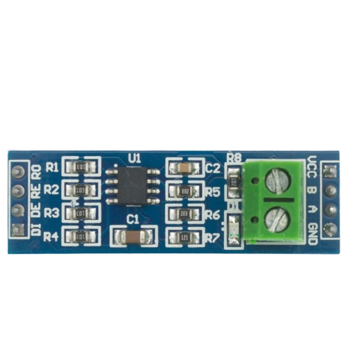
Pin Configuration and Descriptions
| Pin Number | Name | Description |
|---|---|---|
| 1 | VCC | Power supply input (3.3V to 5V) |
| 2 | A | Non-inverting receiver input and driver output |
| 3 | B | Inverting receiver input and driver output |
| 4 | GND | Ground reference for power and signals |
| 5 | RO | Receiver output |
| 6 | RE | Receiver enable (active low) |
| 7 | DE | Driver enable (active high) |
| 8 | DI | Driver input |
Usage Instructions
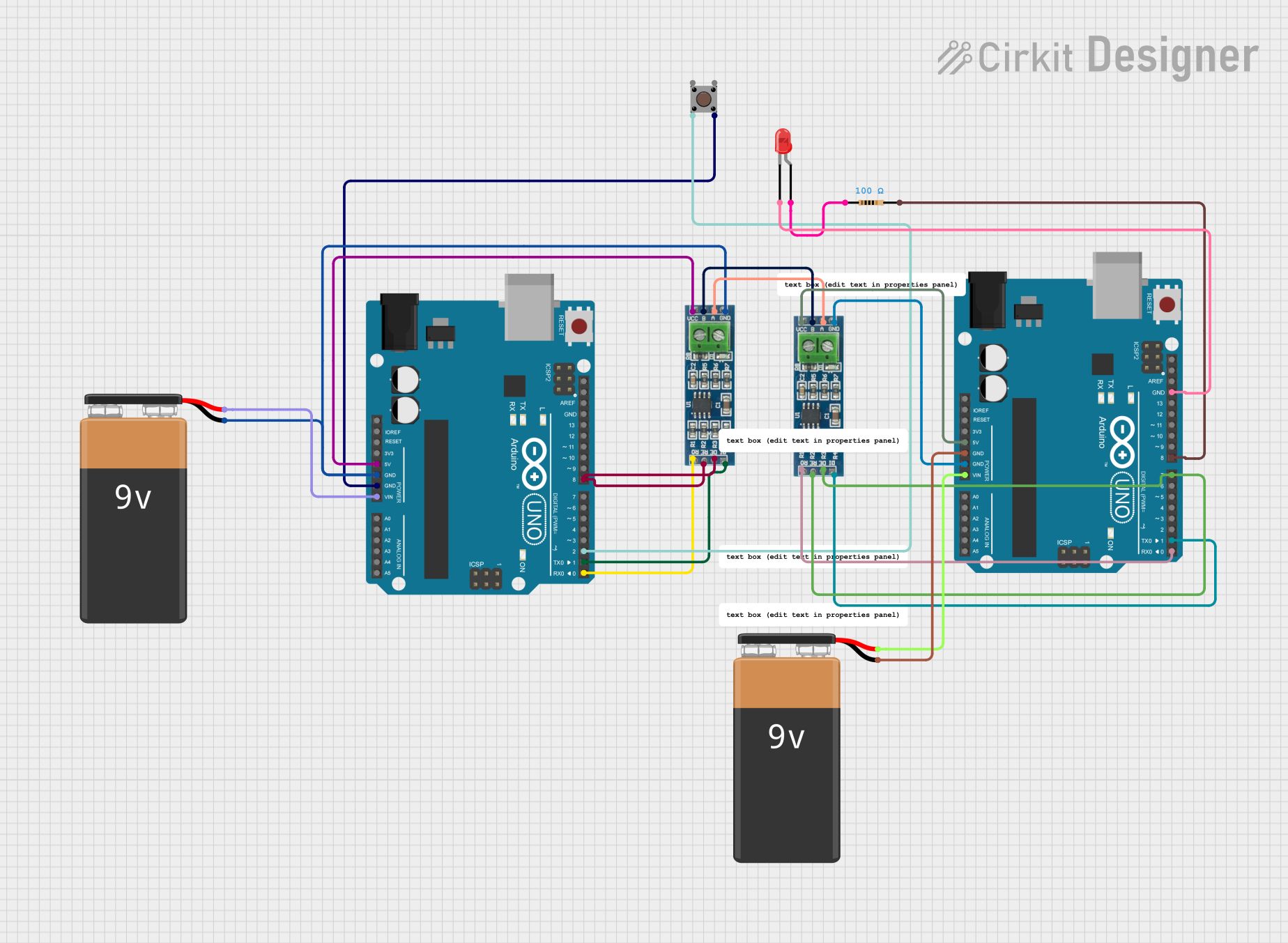
How to Use the Component in a Circuit
- Power Supply: Connect VCC to a 3.3V or 5V power source and GND to the system ground.
- Signal Connection: Connect the A and B pins to the differential twisted pair cable. Ensure that the cable is terminated with a 120 Ohm resistor at both ends of the bus.
- Data Interface: Connect the DI pin to the transmitting output of your microcontroller and the RO pin to the receiving input.
- Enable Pins: Control the RE and DE pins to switch between receiving and transmitting modes. Typically, these can be tied together and driven by a single GPIO pin if half-duplex communication is sufficient.
Important Considerations and Best Practices
- Ensure proper termination of the bus to prevent signal reflections.
- Use twisted pair cables to minimize electromagnetic interference.
- Avoid ground loops by having a single, common ground point.
- Keep the bus as linear as possible, avoiding star configurations.
- Use repeaters for extending the number of nodes beyond 32 or for longer distances.
Troubleshooting and FAQs
Common Issues Users Might Face
- Data Corruption: This can be due to improper termination, ground loops, or interference. Check the cable integrity and termination resistors.
- No Communication: Ensure that the power supply is adequate and that the A and B lines are not reversed.
- Partial Communication: If only some devices are communicating, there may be an issue with the bus topology or a faulty node.
Solutions and Tips for Troubleshooting
- Verify the power supply voltage and ground connections.
- Check the termination resistors at both ends of the bus.
- Ensure that the cable is not damaged and is properly shielded.
- Test each node individually to isolate a faulty device.
FAQs
Q: Can I connect more than 32 devices to an RS-485 bus?
- A: Yes, but you may need to use repeaters or devices with high-impedance receivers to do so.
Q: What is the maximum distance I can achieve with RS-485?
- A: The maximum distance is approximately 4000 feet, but this can vary based on the data rate and cable quality.
Q: Can RS-485 modules be used for full-duplex communication?
- A: Standard RS-485 is half-duplex, but full-duplex can be achieved using four wires (two twisted pairs) and appropriate module configurations.
Example Code for Arduino UNO
#include <SoftwareSerial.h>

// RS-485 Module connection pins
#define RO_PIN 10
#define DI_PIN 11
#define RE_DE_PIN 12

SoftwareSerial rs485(RO_PIN, DI_PIN); // RX, TX

void setup() {
  // Initialize RS-485 communication
  rs485.begin(9600);
  pinMode(RE_DE_PIN, OUTPUT);
  digitalWrite(RE_DE_PIN, LOW); // Enable receiver by default
}

void loop() {
  // To transmit data
  digitalWrite(RE_DE_PIN, HIGH); // Enable transmitter
  rs485.write("Hello RS-485");
  digitalWrite(RE_DE_PIN, LOW); // Disable transmitter to receive data

  // To receive data
  if (rs485.available()) {
    String received = rs485.readString();
    // Process received data
  }

  // Add a delay between transmissions
  delay(1000);
}
Note: The example code provided is for illustrative purposes and may require modifications to work with specific RS-485 modules and Arduino boards. Always refer to the module's datasheet and the Arduino's documentation for accurate pin assignments and configurations.