Cirkit Designer Logo
Cirkit Designer
Your all-in-one circuit design IDE
Home / 
Component Documentation

How to Use FR207: Examples, Pinouts, and Specs

Image of FR207
Cirkit Designer LogoDesign with FR207 in Cirkit Designer

Introduction

The FR207 is a fast recovery rectifier diode that is designed for use in power supplies and other electronic circuits where fast switching is required. Its high-speed switching capability and low forward voltage drop make it ideal for high-frequency rectification and freewheeling applications in converters and inverters, as well as for use in power management tasks.

Explore Projects Built with FR207

Use Cirkit Designer to design, explore, and prototype these projects online. Some projects support real-time simulation. Click "Open Project" to start designing instantly!
Battery-Powered Emergency Alert System with NUCLEO-F072RB, SIM800L, and GPS NEO 6M
Image of women safety: A project utilizing FR207 in a practical application
This circuit is an emergency alert system that uses a NUCLEO-F072RB microcontroller to send SMS alerts and make calls via a SIM800L GSM module, while obtaining location data from a GPS NEO 6M module. The system is powered by a Li-ion battery and includes a TP4056 module for battery charging and protection, with a rocker switch to control power to the microcontroller.
Cirkit Designer LogoOpen Project in Cirkit Designer
IoT-Enabled Environmental Monitoring System with NUCLEO-F303RE and ESP8266
Image of GAS LEAKAGE DETECTION: A project utilizing FR207 in a practical application
This circuit features a NUCLEO-F303RE microcontroller board interfaced with various modules for sensing, actuation, and communication. It includes an MQ-2 gas sensor for detecting combustible gases, a buzzer for audible alerts, and a relay for controlling high-power devices. Additionally, the circuit uses an ESP8266 WiFi module for wireless connectivity and an I2C LCD display for user interface and data display.
Cirkit Designer LogoOpen Project in Cirkit Designer
Battery-Powered ESP32-S3 Controlled Servo System with gForceJoint UART
Image of Copy of Oymotion: A project utilizing FR207 in a practical application
This circuit is a servo control system powered by a 4 x AAA battery pack, regulated by a step-down DC regulator. An ESP32-S3 microcontroller controls five servos and communicates with a gForceJoint UART sensor, enabling precise servo movements based on sensor inputs.
Cirkit Designer LogoOpen Project in Cirkit Designer
Arduino Nano Controlled Fingerprint-Authenticated Servo Lock
Image of Fingerprint_Door_Lock: A project utilizing FR207 in a practical application
This circuit features an Arduino Nano microcontroller interfaced with an r307 fingerprint sensor and a servo motor. The Arduino communicates with the r307 sensor via digital pins D2 and D3 for RX/TX serial communication and controls the servo motor through the PWM signal on pin D8. Power is managed through a rocker switch connected to an 18650 Li-Ion battery, which supplies power to the Arduino's VIN pin and, through the Arduino, to the servo and sensor.
Cirkit Designer LogoOpen Project in Cirkit Designer

Explore Projects Built with FR207

Use Cirkit Designer to design, explore, and prototype these projects online. Some projects support real-time simulation. Click "Open Project" to start designing instantly!
Image of women safety: A project utilizing FR207 in a practical application
Battery-Powered Emergency Alert System with NUCLEO-F072RB, SIM800L, and GPS NEO 6M
This circuit is an emergency alert system that uses a NUCLEO-F072RB microcontroller to send SMS alerts and make calls via a SIM800L GSM module, while obtaining location data from a GPS NEO 6M module. The system is powered by a Li-ion battery and includes a TP4056 module for battery charging and protection, with a rocker switch to control power to the microcontroller.
Cirkit Designer LogoOpen Project in Cirkit Designer
Image of GAS LEAKAGE DETECTION: A project utilizing FR207 in a practical application
IoT-Enabled Environmental Monitoring System with NUCLEO-F303RE and ESP8266
This circuit features a NUCLEO-F303RE microcontroller board interfaced with various modules for sensing, actuation, and communication. It includes an MQ-2 gas sensor for detecting combustible gases, a buzzer for audible alerts, and a relay for controlling high-power devices. Additionally, the circuit uses an ESP8266 WiFi module for wireless connectivity and an I2C LCD display for user interface and data display.
Cirkit Designer LogoOpen Project in Cirkit Designer
Image of Copy of Oymotion: A project utilizing FR207 in a practical application
Battery-Powered ESP32-S3 Controlled Servo System with gForceJoint UART
This circuit is a servo control system powered by a 4 x AAA battery pack, regulated by a step-down DC regulator. An ESP32-S3 microcontroller controls five servos and communicates with a gForceJoint UART sensor, enabling precise servo movements based on sensor inputs.
Cirkit Designer LogoOpen Project in Cirkit Designer
Image of Fingerprint_Door_Lock: A project utilizing FR207 in a practical application
Arduino Nano Controlled Fingerprint-Authenticated Servo Lock
This circuit features an Arduino Nano microcontroller interfaced with an r307 fingerprint sensor and a servo motor. The Arduino communicates with the r307 sensor via digital pins D2 and D3 for RX/TX serial communication and controls the servo motor through the PWM signal on pin D8. Power is managed through a rocker switch connected to an 18650 Li-Ion battery, which supplies power to the Arduino's VIN pin and, through the Arduino, to the servo and sensor.
Cirkit Designer LogoOpen Project in Cirkit Designer

Common Applications

  • Switching power supplies
  • Power converters and inverters
  • Freewheeling diodes in motor control circuits
  • High-frequency rectification circuits

Technical Specifications

Key Technical Details

Parameter Value
Maximum Repetitive Reverse Voltage (Vrrm) 1000 V
Maximum RMS Voltage (Vrms) 700 V
Maximum DC Blocking Voltage (Vdc) 1000 V
Average Forward Rectified Current (Io) 2.0 A
Peak Forward Surge Current (Ifsm) 50 A
Maximum Instantaneous Forward Voltage (Vf) 1.3 V @ 2.0 A
Maximum Reverse Current (Ir) 5 µA @ 1000 V
Recovery Time (trr) 500 ns

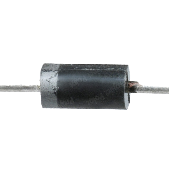
Pin Configuration and Descriptions

The FR207 is a two-terminal device with the following pin configuration:

Pin Description
Anode (A) The terminal through which the conventional current enters the diode.
Cathode (K) The terminal through which the conventional current exits the diode.

Usage Instructions

How to Use the FR207 in a Circuit

  1. Identify the Anode and Cathode: The anode is typically marked by a color band. Ensure correct polarity by connecting the anode to the positive voltage.
  2. Circuit Integration: Place the FR207 in the circuit where rectification is required. It can be used in series with the load or parallel for freewheeling applications.
  3. Heat Management: If the diode is expected to carry continuous high currents, consider using a heat sink to dissipate heat and prevent overheating.

Important Considerations and Best Practices

  • Reverse Voltage: Do not exceed the maximum repetitive reverse voltage rating to avoid breakdown.
  • Surge Current: Ensure that the surge currents do not exceed the peak forward surge current rating.
  • Mounting: Secure the diode firmly to the PCB to ensure mechanical stability and to facilitate heat dissipation.
  • Safety: Always follow standard safety procedures when working with electronic components to prevent injury or damage.

Troubleshooting and FAQs

Common Issues

  • Diode not conducting: Check for correct polarity and ensure that the diode is not placed backward.
  • Overheating: Verify that the current through the diode does not exceed its rated average forward rectified current. Use a heat sink if necessary.
  • Unexpected voltage drops: Ensure that the forward voltage drop is accounted for in the circuit design.

Solutions and Tips for Troubleshooting

  • Polarity Check: Use a multimeter in diode mode to check the anode-to-cathode direction for proper forward bias.
  • Heat Dissipation: If overheating is observed, improve heat dissipation by adding a heat sink or improving airflow.
  • Replacement: If the diode is damaged (e.g., due to overvoltage or overcurrent), it should be replaced with a new one.

FAQs

Q: Can the FR207 be used in AC circuits? A: Yes, the FR207 can rectify AC voltage, but it will only conduct during one half of the AC cycle. For full-wave rectification, use two diodes in a bridge configuration or use a diode bridge rectifier.

Q: What is the significance of the fast recovery time? A: Fast recovery time is crucial in high-frequency circuits as it allows the diode to switch off more quickly, reducing losses and improving efficiency.

Q: Is it necessary to use a heat sink with the FR207? A: It depends on the current it is carrying and the ambient temperature. If the diode is operating near its maximum rated current, a heat sink is recommended to prevent overheating.

Example Circuit: FR207 with Arduino UNO

The following is a simple example of how to use the FR207 diode to protect an Arduino UNO from reverse voltage damage.

// No specific code is required for the diode itself, as it is a passive component.
// However, the diode can be included in circuits to protect against reverse polarity.

void setup() {
  // Setup code here
}

void loop() {
  // Main code here
}

// Connect the anode of the FR207 to the positive power supply line.
// Connect the cathode of the FR207 to the VIN pin of the Arduino UNO.
// If the power supply is accidentally reversed, the diode will block current,
// protecting the Arduino from damage.

Remember, the FR207 is a passive component and does not require code to function. The example above illustrates how the diode can be used in conjunction with an Arduino UNO to provide reverse voltage protection.