How to Use MAX30100: Examples, Pinouts, and Specs
Introduction
The MAX30100 is a low-power, integrated pulse oximeter and heart-rate monitor sensor. It uses photoplethysmography (PPG) technology to measure blood oxygen saturation (SpO2) and heart rate by emitting light through the skin and detecting changes in light absorption. This compact sensor is ideal for wearable devices, fitness trackers, and medical monitoring systems.
Explore Projects Built with MAX30100


Explore Projects Built with MAX30100
Common Applications and Use Cases
- Wearable health monitoring devices
- Fitness trackers
- Medical-grade pulse oximeters
- Heart rate monitoring systems
- IoT health applications
Technical Specifications
The MAX30100 is designed for low-power operation and high accuracy. Below are its key technical details:
| Parameter | Value |
|---|---|
| Operating Voltage | 1.8V (core) and 3.3V (I/O) |
| Supply Current | 600 µA (typical) |
| Standby Current | 0.7 µA |
| Measurement Modes | SpO2 and Heart Rate |
| Communication Interface | I2C (7-bit address: 0x57) |
| LED Wavelengths | Red: 660 nm, IR: 880 nm |
| Sampling Rate | Programmable (50 Hz to 100 Hz) |
| Operating Temperature | -40°C to +85°C |
| Package | 14-pin optical module |
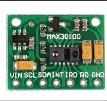
Pin Configuration and Descriptions
The MAX30100 has 14 pins, but only a subset is typically used in most applications. Below is the pin configuration:
| Pin Number | Pin Name | Description |
|---|---|---|
| 1 | SDA | I2C Data Line |
| 2 | SCL | I2C Clock Line |
| 3 | INT | Interrupt Output (active low) |
| 4 | GND | Ground |
| 5 | VIN | Power Supply (1.8V to 3.3V) |
| 6 | IR_DRV | Infrared LED Driver |
| 7 | RED_DRV | Red LED Driver |
| 8-14 | NC | Not Connected (reserved for internal use) |
Usage Instructions
The MAX30100 is straightforward to use in a circuit, especially with microcontrollers like the Arduino UNO. Below are the steps to integrate and use the sensor:
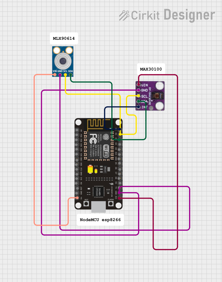
Connecting the MAX30100 to an Arduino UNO
Wiring:
- Connect the
SDApin of the MAX30100 to the Arduino'sA4pin. - Connect the
SCLpin of the MAX30100 to the Arduino'sA5pin. - Connect the
VINpin of the MAX30100 to the Arduino's3.3Vpin. - Connect the
GNDpin of the MAX30100 to the Arduino'sGNDpin. - Optionally, connect the
INTpin to a digital pin on the Arduino for interrupt-based operation.
- Connect the
Install Required Libraries:
- Use the Arduino IDE Library Manager to install the "MAX30100" library or download it from a trusted source like GitHub.
Sample Code: Below is an example Arduino sketch to read heart rate and SpO2 data from the MAX30100:
#include <Wire.h>
#include "MAX30100_PulseOximeter.h"

// Create an instance of the PulseOximeter class
PulseOximeter pox;

// Variable to store the last update time
uint32_t lastUpdate = 0;

// Callback function to handle new data
void onBeatDetected() {
    Serial.println("Beat detected!");
}

void setup() {
    // Initialize serial communication
    Serial.begin(9600);
    Serial.println("Initializing MAX30100...");

    // Initialize the MAX30100 sensor
    if (!pox.begin()) {
        Serial.println("Failed to initialize MAX30100. Check connections!");
        while (1);
    }

    // Set the callback for beat detection
    pox.setOnBeatDetectedCallback(onBeatDetected);

    Serial.println("MAX30100 initialized successfully.");
}

void loop() {
    // Update the sensor readings
    pox.update();

    // Print data every 1 second
    if (millis() - lastUpdate > 1000) {
        lastUpdate = millis();
        Serial.print("Heart Rate: ");
        Serial.print(pox.getHeartRate());
        Serial.print(" bpm, SpO2: ");
        Serial.print(pox.getSpO2());
        Serial.println(" %");
    }
}
Important Considerations and Best Practices
- Power Supply: Ensure the sensor is powered with a stable 3.3V supply. Avoid using 5V as it may damage the sensor.
- I2C Pull-Up Resistors: The I2C lines (
SDAandSCL) require pull-up resistors (typically 4.7kΩ). Some breakout boards include these resistors; check your board's documentation. - Ambient Light: Minimize ambient light interference by enclosing the sensor in a dark environment or using it in low-light conditions.
- Skin Contact: For accurate readings, ensure the sensor is in firm contact with the skin, preferably on a fingertip or earlobe.
Troubleshooting and FAQs
Common Issues and Solutions
No Data Output:
- Verify the wiring connections, especially the
SDAandSCLlines. - Ensure the I2C address (0x57) matches the library or code configuration.
- Verify the wiring connections, especially the
Inaccurate Readings:
- Check for proper skin contact with the sensor.
- Reduce ambient light interference by shielding the sensor.
Sensor Not Detected:
- Confirm that the MAX30100 is powered correctly (3.3V).
- Use an I2C scanner sketch to verify the sensor's address.
Intermittent Data:
- Ensure the I2C pull-up resistors are present and correctly valued.
- Check for loose connections or poor soldering.
FAQs
Q: Can the MAX30100 measure SpO2 and heart rate simultaneously?
A: Yes, the MAX30100 can measure both SpO2 and heart rate simultaneously. However, ensure the sensor is properly configured in your code.
Q: What is the maximum sampling rate of the MAX30100?
A: The MAX30100 supports a programmable sampling rate of up to 100 Hz.
Q: Can I use the MAX30100 with a 5V microcontroller?
A: Yes, but you must use a logic level shifter to convert the 5V I2C signals to 3.3V to avoid damaging the sensor.
Q: How do I improve measurement accuracy?
A: Ensure proper skin contact, minimize motion, and reduce ambient light interference for the best results.