Cirkit Designer Logo
Cirkit Designer
Your all-in-one circuit design IDE
Home / 
Component Documentation

How to Use BMS 1S1P 3.7V 3A (for 18650): Examples, Pinouts, and Specs

Image of BMS 1S1P 3.7V 3A (for 18650)
Cirkit Designer LogoDesign with BMS 1S1P 3.7V 3A (for 18650) in Cirkit Designer

Introduction

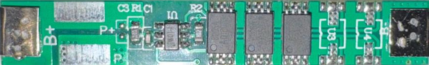
The BMS 1S1P 3.7V 3A is a Battery Management System designed for single series (1S) and single parallel (1P) configurations of 3.7V lithium-ion cells, typically 18650 cells. This component is essential for ensuring the safety and longevity of lithium-ion batteries by protecting them from overcharging, over-discharging, and short circuits. It is widely used in various applications, including portable electronics, DIY battery packs, and renewable energy systems.

Explore Projects Built with BMS 1S1P 3.7V 3A (for 18650)

Use Cirkit Designer to design, explore, and prototype these projects online. Some projects support real-time simulation. Click "Open Project" to start designing instantly!
Battery-Powered 18650 Li-ion Charger with USB Output and Adjustable Voltage Regulator
Image of Breadboard: A project utilizing BMS 1S1P 3.7V 3A (for 18650) in a practical application
This circuit is a battery management and power supply system that uses three 3.7V batteries connected to a 3S 10A Li-ion 18650 Charger Protection Board Module for balanced charging and protection. The system includes a TP4056 Battery Charging Protection Module for additional charging safety, a Step Up Boost Power Converter to regulate and boost the voltage, and a USB regulator to provide a stable 5V output, controlled by a push switch.
Cirkit Designer LogoOpen Project in Cirkit Designer
18650 Li-ion Battery Pack with BMS for 5V Power Supply
Image of battary: A project utilizing BMS 1S1P 3.7V 3A (for 18650) in a practical application
This circuit consists of a battery management system (BMS) connected to a series of 18650 Li-ion batteries arranged in a 4S configuration to provide a regulated output voltage. The BMS ensures safe charging and discharging of the batteries, while a connector provides a 5V output for external devices.
Cirkit Designer LogoOpen Project in Cirkit Designer
Battery-Powered Adjustable Voltage Regulator with Li-ion 18650 Batteries and BMS
Image of mini ups: A project utilizing BMS 1S1P 3.7V 3A (for 18650) in a practical application
This circuit is a power management system that uses four Li-ion 18650 batteries connected to a 2S 30A BMS for battery management and protection. The system includes step-up and step-down voltage regulators to provide adjustable output voltages, controlled by a rocker switch, and multiple DC jacks for power input and output.
Cirkit Designer LogoOpen Project in Cirkit Designer
3S 18650 Battery Pack with Protection Board for Safe Charging
Image of 4S BMS: A project utilizing BMS 1S1P 3.7V 3A (for 18650) in a practical application
This circuit consists of three 18650 batteries connected in series to a 3S 10A Li-ion 18650 Charger Protection Board Module. The protection board manages the charging and discharging of the battery pack, ensuring safe operation by balancing the cells and providing overcharge, over-discharge, and short-circuit protection.
Cirkit Designer LogoOpen Project in Cirkit Designer

Explore Projects Built with BMS 1S1P 3.7V 3A (for 18650)

Use Cirkit Designer to design, explore, and prototype these projects online. Some projects support real-time simulation. Click "Open Project" to start designing instantly!
Image of Breadboard: A project utilizing BMS 1S1P 3.7V 3A (for 18650) in a practical application
Battery-Powered 18650 Li-ion Charger with USB Output and Adjustable Voltage Regulator
This circuit is a battery management and power supply system that uses three 3.7V batteries connected to a 3S 10A Li-ion 18650 Charger Protection Board Module for balanced charging and protection. The system includes a TP4056 Battery Charging Protection Module for additional charging safety, a Step Up Boost Power Converter to regulate and boost the voltage, and a USB regulator to provide a stable 5V output, controlled by a push switch.
Cirkit Designer LogoOpen Project in Cirkit Designer
Image of battary: A project utilizing BMS 1S1P 3.7V 3A (for 18650) in a practical application
18650 Li-ion Battery Pack with BMS for 5V Power Supply
This circuit consists of a battery management system (BMS) connected to a series of 18650 Li-ion batteries arranged in a 4S configuration to provide a regulated output voltage. The BMS ensures safe charging and discharging of the batteries, while a connector provides a 5V output for external devices.
Cirkit Designer LogoOpen Project in Cirkit Designer
Image of mini ups: A project utilizing BMS 1S1P 3.7V 3A (for 18650) in a practical application
Battery-Powered Adjustable Voltage Regulator with Li-ion 18650 Batteries and BMS
This circuit is a power management system that uses four Li-ion 18650 batteries connected to a 2S 30A BMS for battery management and protection. The system includes step-up and step-down voltage regulators to provide adjustable output voltages, controlled by a rocker switch, and multiple DC jacks for power input and output.
Cirkit Designer LogoOpen Project in Cirkit Designer
Image of 4S BMS: A project utilizing BMS 1S1P 3.7V 3A (for 18650) in a practical application
3S 18650 Battery Pack with Protection Board for Safe Charging
This circuit consists of three 18650 batteries connected in series to a 3S 10A Li-ion 18650 Charger Protection Board Module. The protection board manages the charging and discharging of the battery pack, ensuring safe operation by balancing the cells and providing overcharge, over-discharge, and short-circuit protection.
Cirkit Designer LogoOpen Project in Cirkit Designer

Technical Specifications

Key Technical Details

Parameter Value
Battery Configuration 1S1P
Nominal Voltage 3.7V
Maximum Current 3A
Overcharge Protection 4.25V ± 0.05V
Over-discharge Protection 2.5V ± 0.1V
Short Circuit Protection Yes
Operating Temperature -20°C to 60°C
Storage Temperature -40°C to 85°C

Pin Configuration and Descriptions

Pin Name Description
B+ Battery positive terminal
B- Battery negative terminal
P+ Power output positive terminal
P- Power output negative terminal

Usage Instructions

How to Use the Component in a Circuit

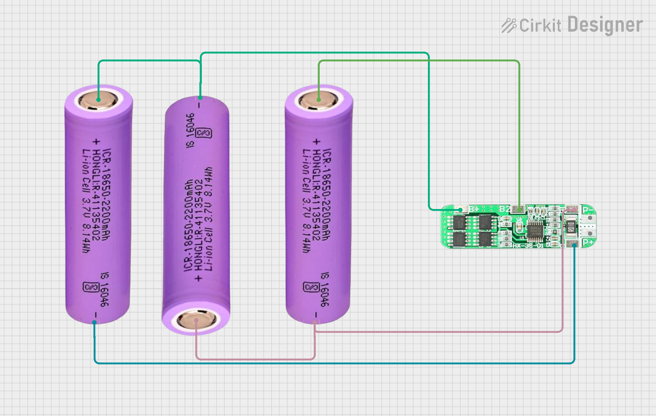
  1. Connect the Battery:

    • Connect the positive terminal of the 18650 cell to the B+ pin.
    • Connect the negative terminal of the 18650 cell to the B- pin.
  2. Connect the Load/Charger:

    • Connect the positive terminal of the load or charger to the P+ pin.
    • Connect the negative terminal of the load or charger to the P- pin.
  3. Ensure Proper Connections:

    • Double-check all connections to ensure they are secure and correct.
    • Use appropriate wire gauges to handle the maximum current rating.

Important Considerations and Best Practices

  • Avoid Overloading: Do not exceed the maximum current rating of 3A to prevent damage to the BMS and the battery.
  • Temperature Monitoring: Ensure the operating temperature is within the specified range to maintain optimal performance.
  • Regular Inspections: Periodically check the connections and the condition of the battery to ensure safe operation.
  • Use Quality Components: Use high-quality 18650 cells and connectors to ensure reliability and safety.

Troubleshooting and FAQs

Common Issues Users Might Face

  1. Battery Not Charging:

    • Possible Cause: Overcharge protection activated.
    • Solution: Check the battery voltage. If it is above 4.25V, allow it to discharge slightly before recharging.
  2. Battery Not Discharging:

    • Possible Cause: Over-discharge protection activated.
    • Solution: Check the battery voltage. If it is below 2.5V, recharge the battery.
  3. Short Circuit Protection Triggered:

    • Possible Cause: Short circuit detected.
    • Solution: Inspect the circuit for any short circuits and correct them before reconnecting the battery.

Solutions and Tips for Troubleshooting

  • Check Connections: Ensure all connections are secure and correct.
  • Measure Voltages: Use a multimeter to measure the battery voltage and ensure it is within the specified range.
  • Inspect for Damage: Look for any physical damage to the BMS or the battery and replace if necessary.

Arduino UNO Example Code

If you are using the BMS with an Arduino UNO to monitor the battery voltage, you can use the following example code:

const int batteryPin = A0; // Analog pin connected to battery
float batteryVoltage = 0.0;

void setup() {
  Serial.begin(9600); // Initialize serial communication
}

void loop() {
  int sensorValue = analogRead(batteryPin); // Read the analog value
  batteryVoltage = sensorValue * (5.0 / 1023.0) * 2; // Convert to voltage
  // The factor of 2 is used because of the voltage divider
  Serial.print("Battery Voltage: ");
  Serial.print(batteryVoltage);
  Serial.println(" V");
  delay(1000); // Wait for 1 second before next reading
}

Note: Ensure you use a voltage divider to step down the battery voltage to a safe level for the Arduino's analog input.

By following this documentation, users can effectively utilize the BMS 1S1P 3.7V 3A to protect and manage their 18650 lithium-ion cells, ensuring safe and reliable operation in various applications.