How to Use Joystick module : Examples, Pinouts, and Specs
Introduction
The HW-504 Joystick Module is a versatile input device commonly used in DIY electronics projects. It allows users to add analog input via a simple interface, typically for controlling cursors, objects in games, or for use in robotics. The module includes a two-axis thumb joystick that can move in the X and Y directions and usually features one or more pushbuttons that can be activated by pressing down on the stick.
Explore Projects Built with Joystick module


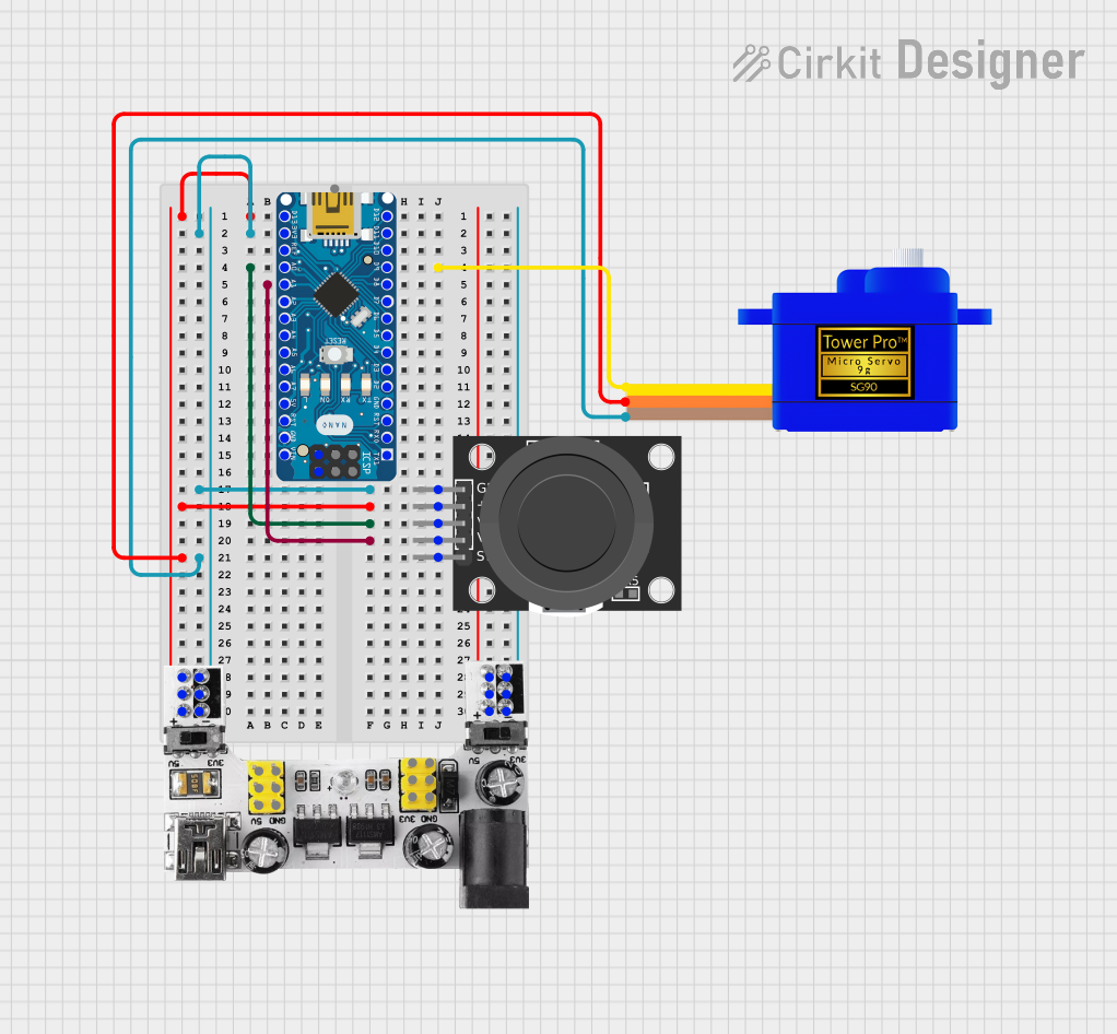
Explore Projects Built with Joystick module
Common Applications and Use Cases
- Gaming controls
- Robotic control interfaces
- Virtual reality navigation
- Educational projects and learning platforms
- User interface for menu selection
Technical Specifications
Key Technical Details
- Operating Voltage: 3.3V to 5V
- Current Consumption: 10mA (typical)
- X and Y-axis dual-axis analog output
- Z-axis pushbutton output
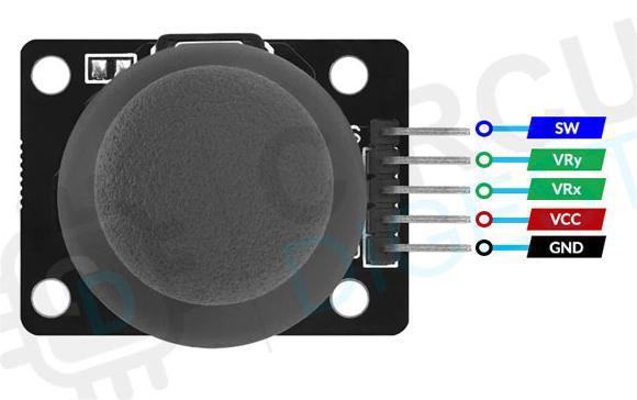
Pin Configuration and Descriptions
| Pin | Description |
|---|---|
| GND | Ground connection |
| +5V | Power supply input (3.3V to 5V) |
| VRx | Analog output for X-axis |
| VRy | Analog output for Y-axis |
| SW | Digital output for pushbutton switch |
Usage Instructions
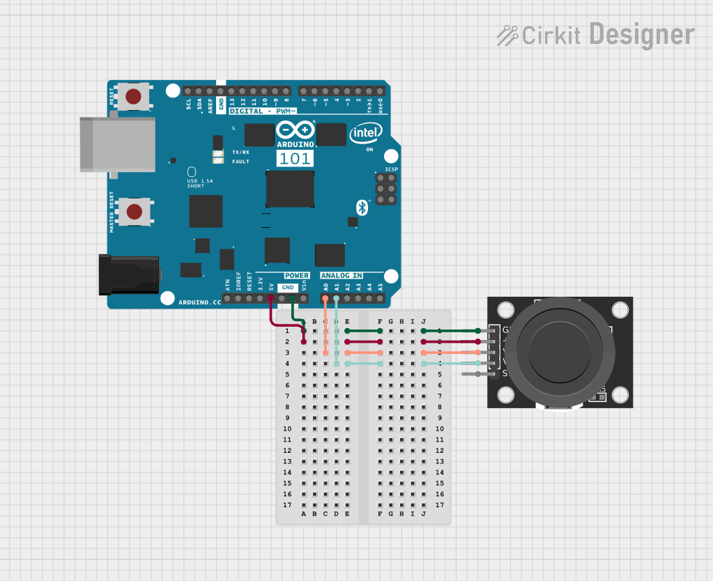
How to Use the Component in a Circuit
- Connect the GND pin to the ground on your microcontroller board.
- Connect the +5V pin to a 3.3V or 5V power supply from your microcontroller board.
- Connect the VRx pin to an analog input pin on your microcontroller to read the X-axis position.
- Connect the VRy pin to another analog input pin on your microcontroller to read the Y-axis position.
- Connect the SW pin to a digital input pin on your microcontroller to read the pushbutton status.
Important Considerations and Best Practices
- Ensure that the power supply matches the operating voltage of the joystick to prevent damage.
- Use pull-up or pull-down resistors on the SW pin if your microcontroller does not have internal pull-up/down resistors.
- Calibrate the joystick's center position in your software to account for any hardware inconsistencies.
- Debounce the pushbutton either in hardware with a capacitor or in software to prevent false triggering.
Example Code for Arduino UNO
// Define the pins for the joystick connections
const int xAxisPin = A0; // Analog input pin for X-axis
const int yAxisPin = A1; // Analog input pin for Y-axis
const int buttonPin = 2; // Digital input pin for pushbutton

void setup() {
  // Initialize the button pin as an input with an internal pull-up resistor
  pinMode(buttonPin, INPUT_PULLUP);
  // Begin serial communication at a baud rate of 9600
  Serial.begin(9600);
}

void loop() {
  // Read the joystick position values
  int xPosition = analogRead(xAxisPin);
  int yPosition = analogRead(yAxisPin);
  // Read the button state (LOW when pressed due to pull-up resistor)
  int buttonState = digitalRead(buttonPin);

  // Print the joystick position values to the serial monitor
  Serial.print("X: ");
  Serial.print(xPosition);
  Serial.print(" | Y: ");
  Serial.print(yPosition);
  Serial.print(" | Button: ");
  Serial.println(buttonState);

  // Add a small delay to prevent overwhelming the serial monitor
  delay(100);
}
Troubleshooting and FAQs
Common Issues Users Might Face
- Joystick not responding: Ensure all connections are secure and the power supply is within the specified range.
- Inaccurate readings: Calibrate the center position in your software and check for any physical obstructions.
- Button not working: Verify the button is connected to the correct pin and that the pull-up resistor is functioning.
Solutions and Tips for Troubleshooting
- Double-check wiring against the pin configuration table.
- Use the Arduino Serial Monitor to debug and monitor joystick values.
- Implement software debouncing for the button if you notice erratic behavior.
FAQs
Q: Can I use this joystick with a 3.3V system? A: Yes, the joystick module can operate at 3.3V, but ensure that all connections are consistent with the 3.3V logic.
Q: How do I interpret the analog values from the joystick? A: The analog values will range from 0 to 1023, with around 512 being the center position for both axes.
Q: What is the function of the SW pin? A: The SW pin is connected to the pushbutton switch on the joystick. It will read LOW when the button is pressed and HIGH otherwise.
Q: How can I improve the precision of the joystick readings? A: Implement software filtering or averaging of multiple readings to reduce noise and improve precision.