Cirkit Designer Logo
Cirkit Designer
Your all-in-one circuit design IDE
Home / 
Component Documentation

How to Use BK-7070G: Examples, Pinouts, and Specs

Image of BK-7070G
Cirkit Designer LogoDesign with BK-7070G in Cirkit Designer

Introduction

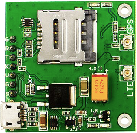
The BK-7070G, manufactured by And-G (Part ID: SIM7070G_Breakout), is a programmable DC power supply designed for laboratory and industrial applications. It features adjustable voltage and current outputs, a digital display for precise monitoring, and multiple protection mechanisms to ensure safe and reliable operation. This versatile power supply is ideal for powering and testing electronic circuits, prototyping, and educational purposes.

Explore Projects Built with BK-7070G

Use Cirkit Designer to design, explore, and prototype these projects online. Some projects support real-time simulation. Click "Open Project" to start designing instantly!
Cellular-Enabled IoT Device with Real-Time Clock and Power Management
Image of LRCM PHASE 2 BASIC: A project utilizing BK-7070G in a practical application
This circuit features a LilyGo-SIM7000G module for cellular communication and GPS functionality, interfaced with an RTC DS3231 for real-time clock capabilities. It includes voltage sensing through two voltage sensor modules, and uses an 8-channel opto-coupler for isolating different parts of the circuit. Power management is handled by a buck converter connected to a DC power source and batteries, with a fuse for protection and a rocker switch for on/off control. Additionally, there's an LED for indication purposes.
Cirkit Designer LogoOpen Project in Cirkit Designer
Battery-Powered Emergency Alert System with NUCLEO-F072RB, SIM800L, and GPS NEO 6M
Image of women safety: A project utilizing BK-7070G in a practical application
This circuit is an emergency alert system that uses a NUCLEO-F072RB microcontroller to send SMS alerts and make calls via a SIM800L GSM module, while obtaining location data from a GPS NEO 6M module. The system is powered by a Li-ion battery and includes a TP4056 module for battery charging and protection, with a rocker switch to control power to the microcontroller.
Cirkit Designer LogoOpen Project in Cirkit Designer
Arduino Mega 2560 Based Security System with Fingerprint Authentication and SMS Alerts
Image of Door security system: A project utilizing BK-7070G in a practical application
This circuit features an Arduino Mega 2560 microcontroller interfaced with a SIM800L GSM module, two fingerprint scanners, an I2C LCD display, an IR sensor, and a piezo buzzer. Power management is handled by a PowerBoost 1000 Basic Pad USB, a TP4056 charging module, and a Li-ion 18650 battery, with an option to use a Mini AC-DC 110V-230V to 5V 700mA module for direct power supply. The primary functionality appears to be a security system with GSM communication capabilities, biometric access control, and visual/audible feedback.
Cirkit Designer LogoOpen Project in Cirkit Designer
Stepper Motor Control System with TB6600 Driver and DKC-1A Controller
Image of Copy of Copy of PLC-Based Step Motor Speed and Direction Control System: A project utilizing BK-7070G in a practical application
This circuit controls a bipolar stepper motor using a tb6600 micro stepping motor driver and a DKC-1A stepper motor controller. The system is powered by a 24VDC power supply and includes a relay module for additional control functionalities.
Cirkit Designer LogoOpen Project in Cirkit Designer

Explore Projects Built with BK-7070G

Use Cirkit Designer to design, explore, and prototype these projects online. Some projects support real-time simulation. Click "Open Project" to start designing instantly!
Image of LRCM PHASE 2 BASIC: A project utilizing BK-7070G in a practical application
Cellular-Enabled IoT Device with Real-Time Clock and Power Management
This circuit features a LilyGo-SIM7000G module for cellular communication and GPS functionality, interfaced with an RTC DS3231 for real-time clock capabilities. It includes voltage sensing through two voltage sensor modules, and uses an 8-channel opto-coupler for isolating different parts of the circuit. Power management is handled by a buck converter connected to a DC power source and batteries, with a fuse for protection and a rocker switch for on/off control. Additionally, there's an LED for indication purposes.
Cirkit Designer LogoOpen Project in Cirkit Designer
Image of women safety: A project utilizing BK-7070G in a practical application
Battery-Powered Emergency Alert System with NUCLEO-F072RB, SIM800L, and GPS NEO 6M
This circuit is an emergency alert system that uses a NUCLEO-F072RB microcontroller to send SMS alerts and make calls via a SIM800L GSM module, while obtaining location data from a GPS NEO 6M module. The system is powered by a Li-ion battery and includes a TP4056 module for battery charging and protection, with a rocker switch to control power to the microcontroller.
Cirkit Designer LogoOpen Project in Cirkit Designer
Image of Door security system: A project utilizing BK-7070G in a practical application
Arduino Mega 2560 Based Security System with Fingerprint Authentication and SMS Alerts
This circuit features an Arduino Mega 2560 microcontroller interfaced with a SIM800L GSM module, two fingerprint scanners, an I2C LCD display, an IR sensor, and a piezo buzzer. Power management is handled by a PowerBoost 1000 Basic Pad USB, a TP4056 charging module, and a Li-ion 18650 battery, with an option to use a Mini AC-DC 110V-230V to 5V 700mA module for direct power supply. The primary functionality appears to be a security system with GSM communication capabilities, biometric access control, and visual/audible feedback.
Cirkit Designer LogoOpen Project in Cirkit Designer
Image of Copy of Copy of PLC-Based Step Motor Speed and Direction Control System: A project utilizing BK-7070G in a practical application
Stepper Motor Control System with TB6600 Driver and DKC-1A Controller
This circuit controls a bipolar stepper motor using a tb6600 micro stepping motor driver and a DKC-1A stepper motor controller. The system is powered by a 24VDC power supply and includes a relay module for additional control functionalities.
Cirkit Designer LogoOpen Project in Cirkit Designer

Common Applications and Use Cases

  • Powering and testing electronic circuits in laboratories
  • Industrial equipment testing and calibration
  • Prototyping and development of electronic devices
  • Educational demonstrations and experiments
  • Battery charging and maintenance

Technical Specifications

Key Technical Details

Parameter Specification
Input Voltage 100-240V AC, 50/60Hz
Output Voltage Range 0-30V DC
Output Current Range 0-5A DC
Display Type Digital LCD with backlight
Voltage Resolution 10mV
Current Resolution 1mA
Protection Features Overvoltage, Overcurrent, Overheat
Operating Temperature 0°C to 40°C
Dimensions 200mm x 150mm x 80mm
Weight 1.5kg

Pin Configuration and Descriptions

The BK-7070G features output terminals and control interfaces for easy integration into various setups. Below is the pin configuration:

Pin/Terminal Name Description
V+ Positive DC output terminal
V- Negative DC output terminal (ground)
USB Port For firmware updates and PC communication
Rotary Knob Adjusts voltage and current settings
Power Switch Turns the power supply on/off

Usage Instructions

How to Use the BK-7070G in a Circuit

  1. Setup and Connection:

    • Connect the BK-7070G to a standard AC power outlet (100-240V AC).
    • Use the V+ and V- terminals to connect the power supply to your circuit or device.
    • Ensure proper polarity when connecting to avoid damage to the circuit.
  2. Adjusting Voltage and Current:

    • Turn on the power supply using the power switch.
    • Use the rotary knob to set the desired output voltage and current.
    • Monitor the digital display to ensure accurate settings.
  3. Operating the Device:

    • Once the desired settings are configured, the power supply will deliver the specified voltage and current to the connected load.
    • The display will show real-time voltage and current readings.
  4. Using the USB Port:

    • Connect the USB port to a PC for firmware updates or remote control via compatible software.

Important Considerations and Best Practices

  • Always verify the voltage and current requirements of your circuit before connecting the BK-7070G.
  • Avoid short-circuiting the output terminals to prevent triggering the overcurrent protection.
  • Operate the device within the specified temperature range (0°C to 40°C) to ensure optimal performance.
  • Use proper ventilation to prevent overheating during prolonged use.

Arduino UNO Integration Example

The BK-7070G can be used to power an Arduino UNO for prototyping. Below is an example of how to connect and use the power supply with an Arduino UNO:

  1. Connect the V+ terminal of the BK-7070G to the VIN pin of the Arduino UNO.
  2. Connect the V- terminal to the GND pin of the Arduino UNO.
  3. Set the output voltage of the BK-7070G to 9V (recommended for Arduino UNO VIN input).
// Example Arduino code to blink an LED
// Connect an LED to pin 13 with a 220-ohm resistor

void setup() {
  pinMode(13, OUTPUT); // Set pin 13 as an output
}

void loop() {
  digitalWrite(13, HIGH); // Turn the LED on
  delay(1000);            // Wait for 1 second
  digitalWrite(13, LOW);  // Turn the LED off
  delay(1000);            // Wait for 1 second
}

Troubleshooting and FAQs

Common Issues and Solutions

Issue Possible Cause Solution
No output voltage Power supply not turned on Ensure the power switch is in the ON position.
Output voltage fluctuates Load exceeds current limit Check and adjust the current limit setting.
Overvoltage or overcurrent warning Circuit is drawing excessive power Verify the circuit's power requirements and adjust settings.
Device overheats Insufficient ventilation Ensure proper airflow around the device.

FAQs

Q: Can the BK-7070G be used to charge batteries?
A: Yes, the BK-7070G can charge batteries. Ensure the voltage and current settings match the battery's specifications.

Q: Is the BK-7070G compatible with PC software?
A: Yes, the USB port allows for PC communication and firmware updates. Check the manufacturer's website for compatible software.

Q: What happens if I short the output terminals?
A: The overcurrent protection will activate to prevent damage. Remove the short circuit and reset the power supply.

Q: Can I use the BK-7070G outdoors?
A: No, the BK-7070G is designed for indoor use only. Protect it from moisture and extreme temperatures.

By following this documentation, users can safely and effectively operate the BK-7070G for a variety of applications.