
How to Use Self Locking push button with LED: Examples, Pinouts, and Specs
 Design with Self Locking push button with LED in Cirkit Designer
Introduction
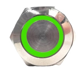
The Self-Locking Push Button with LED (Manufacturer: Generic, Part ID: 001) is a versatile electronic component that combines a push button switch with a locking mechanism and an integrated LED indicator. When pressed, the button locks into place, maintaining its state until pressed again to release. The built-in LED provides a visual indication of the button's status, making it ideal for applications requiring clear feedback.
Explore Projects Built with Self Locking push button with LED
 Open Project in Cirkit Designer
 Open Project in Cirkit Designer
 Open Project in Cirkit Designer
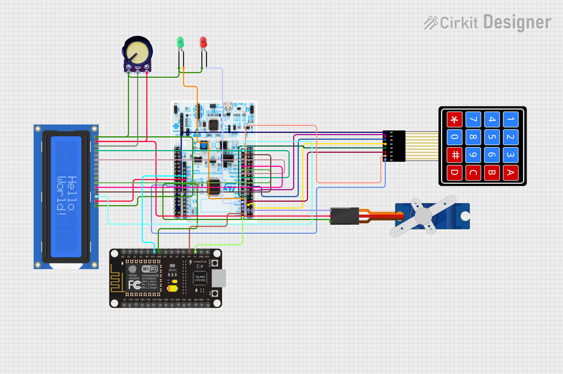 Open Project in Cirkit Designer
Explore Projects Built with Self Locking push button with LED
Open Project in Cirkit DesignerOpen Project in Cirkit DesignerOpen Project in Cirkit DesignerOpen Project in Cirkit DesignerCommon Applications and Use Cases
- Power switches for electronic devices
- Control panels and dashboards
- DIY electronics projects
- Home automation systems
- Industrial equipment controls
Technical Specifications
Below are the key technical details for the Self-Locking Push Button with LED:
| Parameter | Value |
|---|---|
| Operating Voltage | 3V to 24V DC |
| LED Voltage | 3V to 5V DC (with resistor) |
| Maximum Current | 3A |
| Contact Resistance | ≤ 50 mΩ |
| Insulation Resistance | ≥ 100 MΩ |
| Button Type | Self-locking (latching) |
| LED Color | Red (varies by model) |
| Mounting Hole Diameter | 16mm |
| Operating Temperature | -20°C to +55°C |
| Material | Plastic and metal alloy |
Pin Configuration and Descriptions
The Self-Locking Push Button with LED typically has four pins. The table below describes each pin:
| Pin | Label | Description |
|---|---|---|
| 1 | NO | Normally Open terminal for the switch. Connect to the load or circuit input. |
| 2 | COM | Common terminal for the switch. Connect to the power source or ground. |
| 3 | LED+ | Positive terminal for the LED. Connect to a current-limiting resistor and power. |
| 4 | LED- | Negative terminal for the LED. Connect to ground. |
Usage Instructions
How to Use the Component in a Circuit
- Mounting the Button: Drill a 16mm hole in your panel or enclosure and secure the button using the provided nut.
- Wiring the Switch:
- Connect the NO pin to the input of your circuit or load.
- Connect the COM pin to the power source or ground, depending on your circuit design.
- Wiring the LED:
- Connect the LED+ pin to a current-limiting resistor (e.g., 220Ω for 5V systems) and then to the positive voltage supply.
- Connect the LED- pin to ground.
- Testing:
- Press the button to toggle its state. The LED will light up when the button is locked (ON) and turn off when released (OFF).
Important Considerations and Best Practices
- Current Limiting for LED: Always use a resistor in series with the LED to prevent damage due to excessive current.
- Voltage Compatibility: Ensure the operating voltage of the button and LED matches your circuit's power supply.
- Debouncing: For digital circuits, consider implementing hardware or software debouncing to avoid false triggering caused by mechanical bounce.
- Heat Management: Avoid exceeding the maximum current rating (3A) to prevent overheating or damage.
Example: Connecting to an Arduino UNO
Below is an example of how to connect the Self-Locking Push Button with LED to an Arduino UNO:
Circuit Connections
- NO Pin: Connect to Arduino digital pin 2.
- COM Pin: Connect to ground.
- LED+ Pin: Connect to a 220Ω resistor, then to Arduino 5V.
- LED- Pin: Connect to ground.
Arduino Code
// Self-Locking Push Button with LED Example
// This code toggles the LED state based on the button press.

const int buttonPin = 2;  // Pin connected to the NO terminal of the button
const int ledPin = 13;    // Built-in LED on Arduino for testing

void setup() {
  pinMode(buttonPin, INPUT_PULLUP); // Set button pin as input with pull-up resistor
  pinMode(ledPin, OUTPUT);         // Set LED pin as output
}

void loop() {
  // Read the button state (LOW when pressed due to pull-up resistor)
  int buttonState = digitalRead(buttonPin);

  if (buttonState == LOW) {
    // Toggle the LED state
    digitalWrite(ledPin, !digitalRead(ledPin));
    delay(500); // Debounce delay to avoid multiple toggles
  }
}
Troubleshooting and FAQs
Common Issues and Solutions
LED Does Not Light Up:
- Check the polarity of the LED connections (LED+ and LED-).
- Ensure a current-limiting resistor is used and properly connected.
- Verify the power supply voltage matches the LED's operating voltage.
Button Does Not Lock in Place:
- Ensure the button is not physically damaged or obstructed.
- Check for proper mounting and alignment in the panel.
Switch Does Not Toggle the Circuit:
- Verify the connections to the NO and COM pins.
- Check for loose or broken wires in the circuit.
Arduino Does Not Respond to Button Press:
- Ensure the button is connected to the correct Arduino pin.
- Verify the Arduino code and ensure the pinMode is set correctly.
FAQs
Q: Can I use this button with an AC circuit?
A: No, this button is designed for DC circuits only. Using it with AC may damage the component or pose safety risks.
Q: What resistor value should I use for the LED?
A: For a 5V system, a 220Ω resistor is recommended. For other voltages, use Ohm's Law (R = V/I) to calculate the appropriate value.
Q: Can I replace the LED with a different color?
A: Yes, but ensure the replacement LED has a similar forward voltage and current rating.
Q: Is the button waterproof?
A: No, this button is not waterproof. Use it in dry environments or consider a waterproof variant for outdoor applications.