How to Use RELAY: Examples, Pinouts, and Specs
Introduction
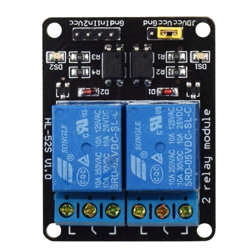
A relay is an electromechanical switch that uses an electromagnet to open or close a circuit. It allows a low-power signal to control a higher power circuit, providing isolation and control in various applications. Relays are widely used in automation, home appliances, automotive systems, and industrial equipment to control high-current devices such as motors, lights, and heaters.
Explore Projects Built with RELAY


Explore Projects Built with RELAY
Common Applications and Use Cases
- Home Automation: Controlling lights, fans, and other appliances.
- Automotive Systems: Switching headlights, horns, and other high-current devices.
- Industrial Control: Managing motors, pumps, and heavy machinery.
- Microcontroller Projects: Allowing low-power microcontrollers (e.g., Arduino) to control high-power devices.
- Safety Systems: Providing electrical isolation between control and power circuits.
Technical Specifications
Below are the general technical specifications for a standard 5V relay module commonly used in electronics projects. Specifications may vary depending on the specific relay model.
Key Technical Details
- Operating Voltage: 5V DC (control signal)
- Trigger Current: ~15-20 mA
- Switching Voltage: Up to 250V AC or 30V DC (load side)
- Switching Current: Up to 10A (load side)
- Contact Type: SPDT (Single Pole Double Throw) or DPDT (Double Pole Double Throw)
- Electrical Isolation: Optocoupler isolation (in some modules)
- Relay Coil Resistance: ~70Ω (for 5V relays)
Pin Configuration and Descriptions
The pin configuration for a typical 5V relay module is as follows:
| Pin Name | Description |
|---|---|
| VCC | Connects to the 5V power supply to power the relay module. |
| GND | Ground connection for the relay module. |
| IN | Control signal input. A HIGH signal activates the relay, and a LOW signal deactivates it. |
| COM | Common terminal for the relay switch. |
| NO | Normally Open terminal. The circuit is open when the relay is inactive. |
| NC | Normally Closed terminal. The circuit is closed when the relay is inactive. |
Usage Instructions
How to Use the Relay in a Circuit
- Power the Relay Module: Connect the VCC pin to a 5V power source and the GND pin to ground.
- Control Signal: Connect the IN pin to a microcontroller (e.g., Arduino) or a control circuit. Use a digital output pin to send HIGH or LOW signals to control the relay.
- Load Connection:
- Connect the device you want to control (e.g., a light bulb or motor) to the COM and NO terminals if you want the circuit to be normally open.
- Use the COM and NC terminals if you want the circuit to be normally closed.
- Isolation: Ensure proper electrical isolation between the control and load sides to prevent damage to the control circuit.
Important Considerations and Best Practices
- Flyback Diode: If you're using a bare relay (not a module), add a flyback diode across the relay coil to protect the control circuit from voltage spikes.
- Power Ratings: Ensure the relay's voltage and current ratings match the load requirements.
- Optocoupler Isolation: Use a relay module with an optocoupler for added safety and isolation.
- External Power Supply: For high-current loads, use an external power supply to power the load side of the relay.
- Avoid Overloading: Do not exceed the relay's maximum current and voltage ratings to prevent damage.
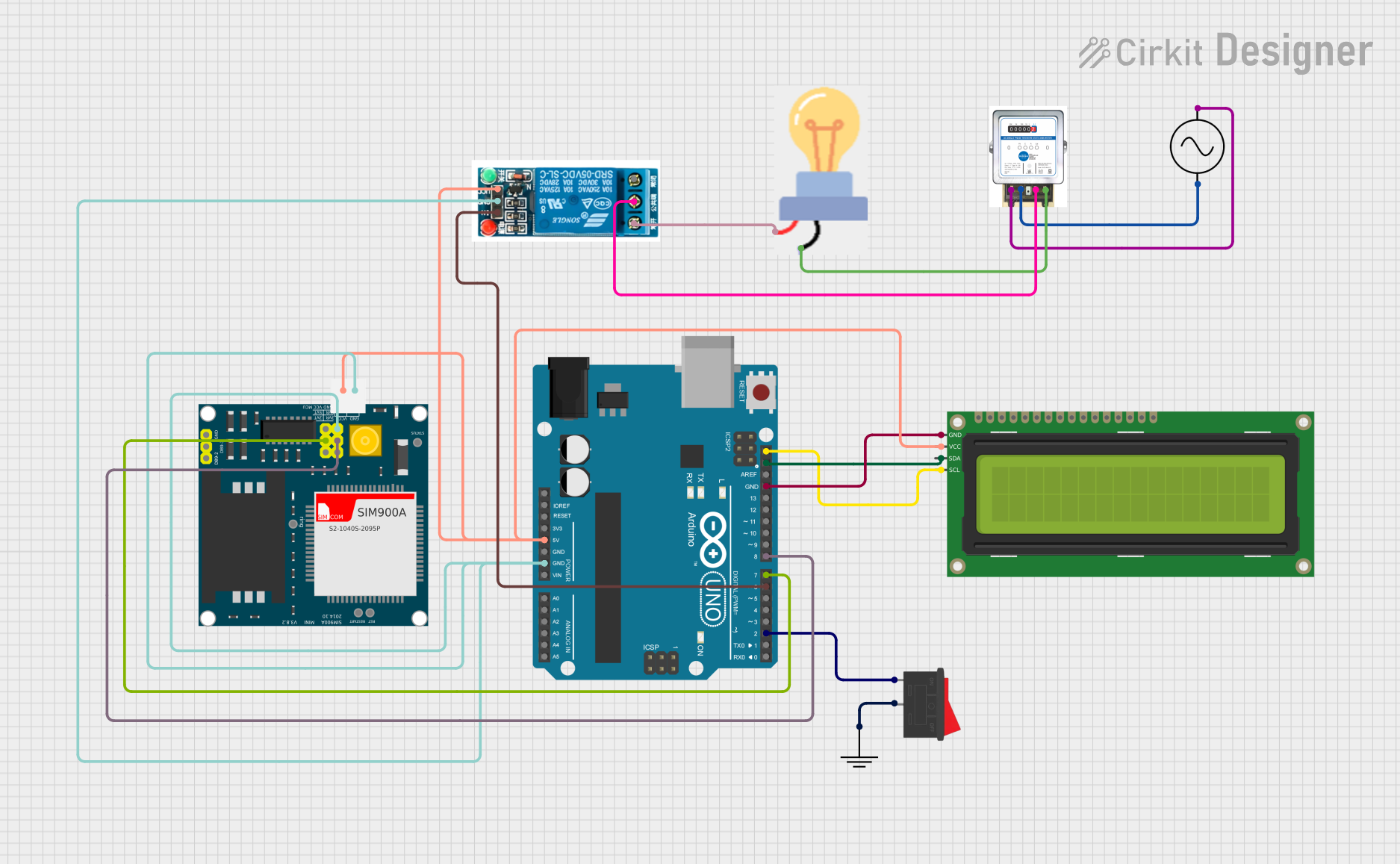
Example: Using a Relay with Arduino UNO
Below is an example of how to control a relay module using an Arduino UNO:
// Example: Controlling a relay module with Arduino UNO
// Connect the relay module's IN pin to Arduino pin 7
// VCC and GND of the relay module should be connected to 5V and GND of Arduino

#define RELAY_PIN 7  // Define the pin connected to the relay module's IN pin

void setup() {
  pinMode(RELAY_PIN, OUTPUT);  // Set the relay pin as an output
  digitalWrite(RELAY_PIN, LOW);  // Ensure the relay is off at startup
}

void loop() {
  digitalWrite(RELAY_PIN, HIGH);  // Turn the relay on
  delay(1000);  // Keep the relay on for 1 second
  digitalWrite(RELAY_PIN, LOW);  // Turn the relay off
  delay(1000);  // Keep the relay off for 1 second
}
Troubleshooting and FAQs
Common Issues and Solutions
Relay Not Activating:
- Cause: Insufficient control signal voltage or current.
- Solution: Ensure the control signal is 5V and the source can supply at least 15-20 mA.
Load Not Switching:
- Cause: Incorrect wiring of the load to the relay terminals.
- Solution: Double-check the connections to the COM, NO, and NC terminals.
Relay Clicking but No Output:
- Cause: Load exceeds the relay's current or voltage rating.
- Solution: Verify the load's specifications and ensure they are within the relay's limits.
Microcontroller Resetting When Relay Activates:
- Cause: Voltage spikes or insufficient power supply.
- Solution: Add a flyback diode across the relay coil and ensure the power supply is adequate.
Relay Module Overheating:
- Cause: Prolonged operation near maximum current rating.
- Solution: Use a relay with a higher current rating or reduce the load.
FAQs
Q: Can I use a 5V relay with a 3.3V microcontroller?
A: Most 5V relays require a 5V control signal. Use a transistor or level shifter to interface a 3.3V microcontroller with the relay.Q: How do I know if my relay is SPDT or DPDT?
A: Check the relay's datasheet or look for the number of terminals. SPDT relays have 5 terminals, while DPDT relays have 8 terminals.Q: Can I control an AC load with a DC relay?
A: Yes, as long as the relay's contact ratings support the AC voltage and current of the load.Q: What is the lifespan of a relay?
A: Relays typically have a lifespan of 100,000 to 1,000,000 operations, depending on the load and usage conditions.