How to Use MP1584EN Power Regulator Board: Examples, Pinouts, and Specs
Introduction
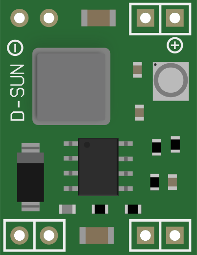
The MP1584EN Power Regulator Board is a compact, high-efficiency, adjustable step-down voltage regulator that uses the MP1584EN integrated circuit to convert higher input voltages to a lower, stable output voltage. This component is widely used in battery-powered devices, DIY electronics, and any application where voltage regulation is necessary to protect sensitive electronics.
Explore Projects Built with MP1584EN Power Regulator Board
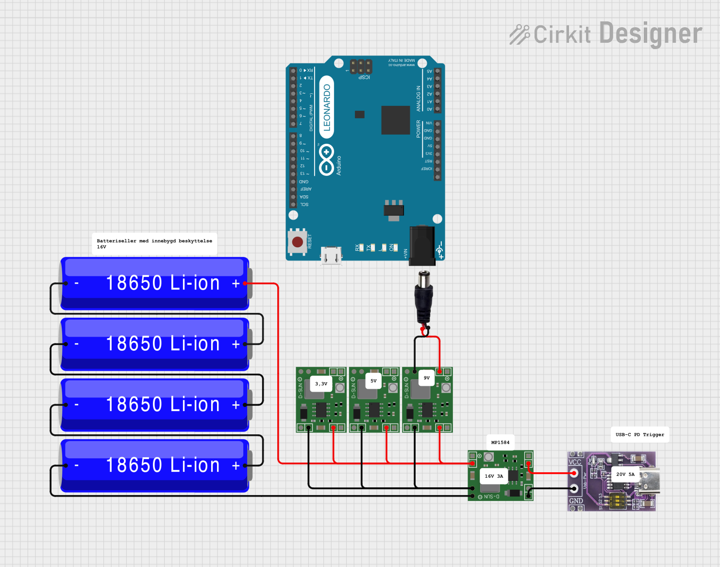


Explore Projects Built with MP1584EN Power Regulator Board
Common Applications and Use Cases
- Power supply for battery-operated devices
- Voltage regulation for microcontrollers and embedded systems
- Power source for LED lighting
- Portable electronics
- DIY projects requiring a stable power supply
Technical Specifications
Key Technical Details
- Input Voltage Range: 4.5V to 28V
- Output Voltage Range: 0.8V to 20V (adjustable via potentiometer)
- Output Current: Up to 3A (adequate heat sinking is required for currents above 2A)
- Switching Frequency: 1.5MHz
- Efficiency: Up to 92%
- Operating Temperature: -40°C to +85°C
Pin Configuration and Descriptions
| Pin Number | Name | Description |
|---|---|---|
| 1 | VIN | Input voltage (4.5V to 28V) |
| 2 | GND | Ground connection |
| 3 | VOUT | Regulated output voltage (0.8V to 20V) |
| 4 | ADJ | Adjustment pin (connected to onboard potentiometer for voltage adjustment) |
Usage Instructions
How to Use the Component in a Circuit
- Connect the input voltage (4.5V to 28V) to the VIN and GND pins.
- Adjust the onboard potentiometer to set the desired output voltage. Use a multimeter to measure the output voltage while adjusting.
- Connect the load to the VOUT and GND pins.
- Ensure that the input voltage is always higher than the desired output voltage.
Important Considerations and Best Practices
- Always verify the output voltage with a multimeter before connecting sensitive electronics.
- Do not exceed the maximum input voltage of 28V to prevent damage to the board.
- The maximum output current is 3A; however, for continuous operation above 2A, adequate heat sinking is necessary.
- Avoid placing the regulator in high-temperature environments to prevent overheating.
- Keep the regulator away from electronic components that are sensitive to high-frequency noise due to the switching frequency of 1.5MHz.
Troubleshooting and FAQs
Common Issues Users Might Face
- Output voltage is too high or too low: Ensure the potentiometer is correctly adjusted. If the issue persists, check for any damage to the potentiometer or the board.
- Regulator is overheating: Check if the current draw is within the specified limit and if adequate heat sinking is provided.
- No output voltage: Verify the input voltage is within the specified range and connections are correct.
Solutions and Tips for Troubleshooting
- If the output voltage cannot be adjusted, replace the potentiometer or the entire board if necessary.
- For overheating issues, reduce the load current or improve heat dissipation by adding a heatsink or improving airflow.
- Double-check wiring and solder joints for any loose connections or shorts.
Example Code for Arduino UNO
The MP1584EN Power Regulator Board can be used to power an Arduino UNO or its peripherals. Below is an example code snippet that demonstrates how to read the output voltage of the regulator using the Arduino's analog input. This can be useful for monitoring the voltage in your application.
// Define the analog pin connected to the VOUT of the regulator
const int voltagePin = A0;

void setup() {
  Serial.begin(9600);
}

void loop() {
  int sensorValue = analogRead(voltagePin); // Read the analog value
  float voltage = sensorValue * (5.0 / 1023.0); // Convert to voltage
  Serial.print("Regulator Output Voltage: ");
  Serial.print(voltage);
  Serial.println(" V");
  delay(1000); // Wait for 1 second before reading again
}
Note: The code assumes that the Arduino's 5V rail is used as a reference voltage and that the output voltage of the regulator is within the 0-5V range. If the output voltage is higher, a voltage divider must be used to bring the voltage within the readable range for the Arduino's analog input.