How to Use DRV8838 Single Brushed DC Motor Driver: Examples, Pinouts, and Specs
Introduction
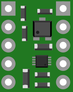
The DRV8838 is a single brushed DC motor driver designed to provide efficient and reliable control of a single brushed DC motor. It features a compact design, making it ideal for space-constrained applications. The DRV8838 supports adjustable speed and direction control, and it includes built-in protection mechanisms such as overcurrent protection, thermal shutdown, and undervoltage lockout. This makes it a robust choice for motor control in a variety of applications.
Explore Projects Built with DRV8838 Single Brushed DC Motor Driver
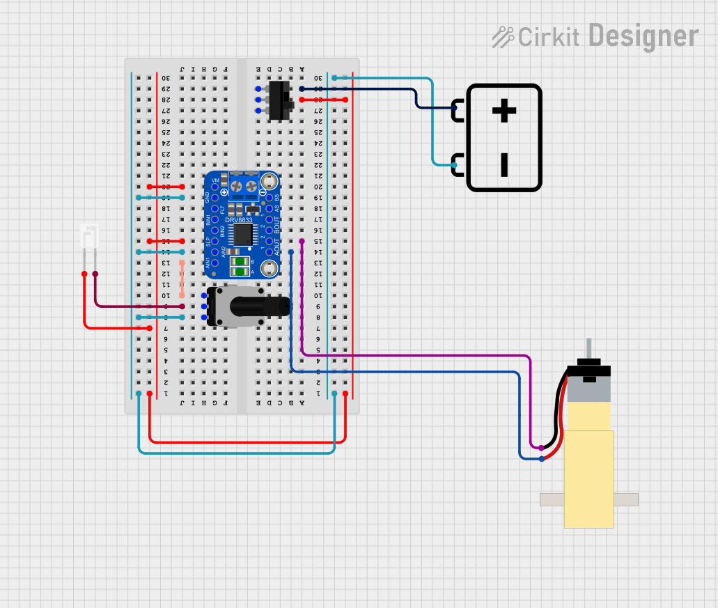
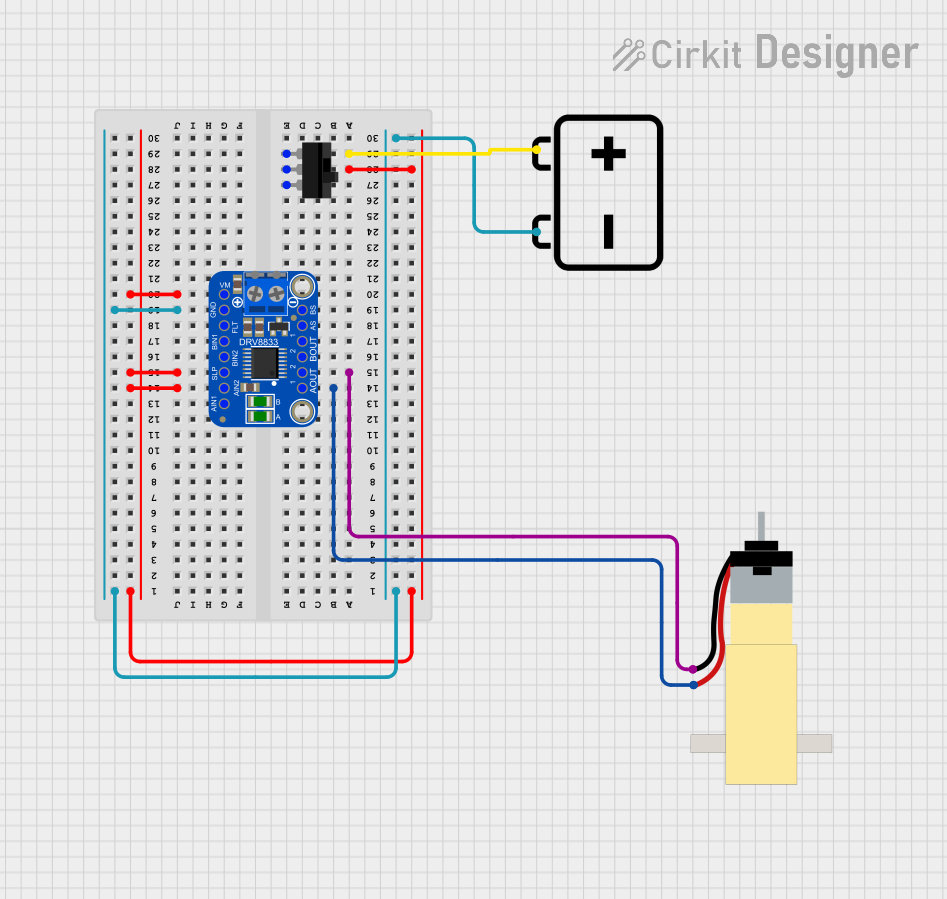

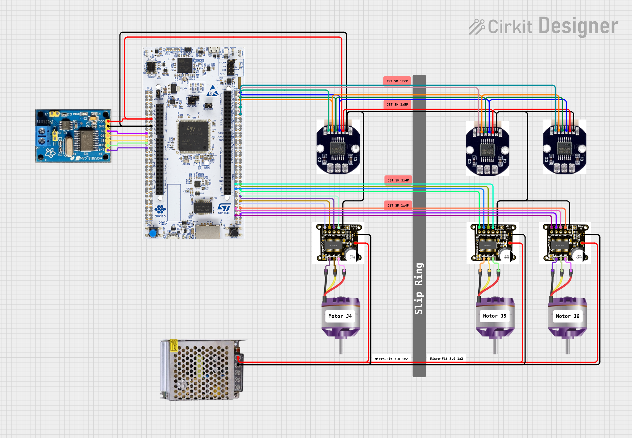
Explore Projects Built with DRV8838 Single Brushed DC Motor Driver
Common Applications and Use Cases
- Robotics and automation systems
- Small electric vehicles
- Industrial equipment
- Consumer electronics
- Educational projects and prototyping
Technical Specifications
Key Technical Details
- Operating Voltage Range: 0 V to 11 V
- Output Current: Up to 1.7 A (continuous), 1.8 A (peak)
- Control Interface: PWM (Pulse Width Modulation) and direction control
- Logic Voltage Range: 1.8 V to 7 V
- Built-in Protections:
- Overcurrent protection
- Thermal shutdown
- Undervoltage lockout
- Operating Temperature Range: -40°C to 150°C
- Package Type: 8-pin WSON (3 mm × 3 mm)
Pin Configuration and Descriptions
The DRV8838 comes in an 8-pin WSON package. Below is the pinout and description:
| Pin | Name | Type | Description |
|---|---|---|---|
| 1 | IN1 | Input | Logic input to control motor direction and speed (PWM capable). |
| 2 | IN2 | Input | Logic input to control motor direction and speed (PWM capable). |
| 3 | nSLEEP | Input | Active-low sleep mode input. Pull high to enable the driver. |
| 4 | GND | Ground | Ground connection for the device. |
| 5 | OUT2 | Output | Motor output terminal 2. |
| 6 | VM | Power Supply | Motor power supply input (0 V to 11 V). |
| 7 | OUT1 | Output | Motor output terminal 1. |
| 8 | nFAULT | Output (Open-Drain) | Fault indicator. Pulled low during fault conditions (e.g., overcurrent). |
Usage Instructions
How to Use the DRV8838 in a Circuit
- Power Supply: Connect the motor power supply (VM) to the VM pin. Ensure the voltage is within the range of 0 V to 11 V.
- Logic Inputs: Use the IN1 and IN2 pins to control the motor's speed and direction:
- Apply a PWM signal to either IN1 or IN2 to control speed.
- Set IN1 high and IN2 low to rotate the motor in one direction.
- Set IN1 low and IN2 high to rotate the motor in the opposite direction.
- Set both IN1 and IN2 low to brake the motor.
- Sleep Mode: Pull the nSLEEP pin high to enable the driver. Pull it low to put the driver into low-power sleep mode.
- Fault Monitoring: Monitor the nFAULT pin for fault conditions. If it is pulled low, check for overcurrent, thermal shutdown, or undervoltage issues.
- Motor Connections: Connect the motor terminals to OUT1 and OUT2.
Important Considerations and Best Practices
- Use a decoupling capacitor (e.g., 10 µF) close to the VM pin to stabilize the power supply.
- Avoid exceeding the maximum current rating to prevent damage to the driver.
- Ensure proper heat dissipation, especially in high-current applications.
- Use pull-up resistors on the nFAULT pin if you need to monitor fault conditions.
- For Arduino or microcontroller-based projects, ensure the logic voltage levels are compatible with the DRV8838's input range (1.8 V to 7 V).
Example Arduino Code
Below is an example of how to control a motor using the DRV8838 with an Arduino UNO:
// Define pin connections
const int IN1 = 9;  // PWM pin for motor control
const int IN2 = 10; // Direction control pin
const int nSLEEP = 8; // Sleep mode pin

void setup() {
  // Set pin modes
  pinMode(IN1, OUTPUT);
  pinMode(IN2, OUTPUT);
  pinMode(nSLEEP, OUTPUT);

  // Enable the motor driver
  digitalWrite(nSLEEP, HIGH);
}

void loop() {
  // Rotate motor in one direction at 50% speed
  analogWrite(IN1, 128); // 50% duty cycle (0-255 scale)
  digitalWrite(IN2, LOW);
  delay(2000); // Run for 2 seconds

  // Rotate motor in the opposite direction at 75% speed
  analogWrite(IN1, 0);   // Stop IN1
  analogWrite(IN2, 192); // 75% duty cycle
  delay(2000); // Run for 2 seconds

  // Brake the motor
  digitalWrite(IN1, LOW);
  digitalWrite(IN2, LOW);
  delay(2000); // Brake for 2 seconds
}
Troubleshooting and FAQs
Common Issues and Solutions
Motor Does Not Spin:
- Ensure the nSLEEP pin is pulled high to enable the driver.
- Verify that the power supply voltage is within the specified range (0 V to 11 V).
- Check the connections to the motor and ensure they are secure.
nFAULT Pin Pulled Low:
- Check for overcurrent conditions. Reduce the motor load if necessary.
- Ensure the driver is not overheating. Improve heat dissipation if needed.
- Verify that the power supply voltage is stable and within range.
Motor Spins in the Wrong Direction:
- Swap the logic levels on the IN1 and IN2 pins to reverse the motor direction.
Driver Overheats:
- Ensure the current draw does not exceed the maximum rating.
- Use a heatsink or improve ventilation around the driver.
FAQs
Can I use the DRV8838 with a 3.3 V microcontroller? Yes, the DRV8838 supports logic voltage levels as low as 1.8 V, making it compatible with 3.3 V systems.
What happens if both IN1 and IN2 are high? The motor will enter a high-impedance state (coast mode), and it will not actively brake.
Is the DRV8838 suitable for battery-powered applications? Yes, its low operating voltage and sleep mode make it ideal for battery-powered systems.
Can I control the speed of the motor? Yes, you can use a PWM signal on the IN1 or IN2 pin to adjust the motor speed.