How to Use 20A Buck 300W cc cv: Examples, Pinouts, and Specs
Introduction
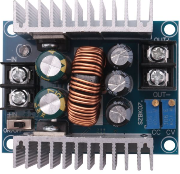
The 20A Buck 300W CC CV by Sene (Manufacturer Part ID: 300W 20A CC CV) is a high-performance DC-DC buck converter designed for applications requiring constant current (CC) and constant voltage (CV) regulation. This module is capable of stepping down input voltages to a stable, adjustable output voltage and current, making it ideal for powering sensitive electronic devices, battery charging, and LED drivers.
Explore Projects Built with 20A Buck 300W cc cv

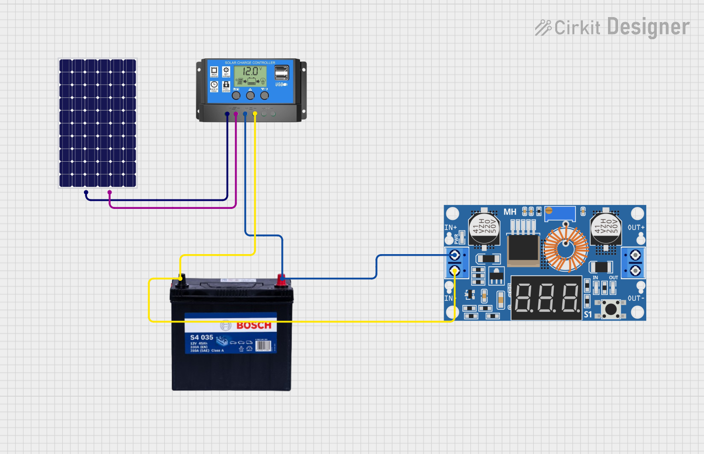


Explore Projects Built with 20A Buck 300W cc cv
Common Applications
- Battery charging (e.g., lithium-ion, lead-acid batteries)
- LED lighting systems
- Powering DC motors
- Laboratory power supplies
- Solar power systems
- General-purpose DC voltage regulation
Technical Specifications
The following table outlines the key technical specifications of the 20A Buck 300W CC CV module:
| Parameter | Value |
|---|---|
| Input Voltage Range | 6V to 40V |
| Output Voltage Range | 1.2V to 36V (adjustable) |
| Output Current Range | 0A to 20A (adjustable) |
| Maximum Power Output | 300W |
| Efficiency | Up to 95% |
| Operating Frequency | 150 kHz |
| Voltage Regulation | Constant Voltage (CV) |
| Current Regulation | Constant Current (CC) |
| Protection Features | Overcurrent, Overtemperature, Short Circuit |
| Dimensions | 60mm x 52mm x 22mm |
Pin Configuration and Descriptions
The module has four main input/output terminals for connection. The table below describes each terminal:
| Terminal | Label | Description |
|---|---|---|
| 1 | VIN+ | Positive input voltage terminal (6V to 40V) |
| 2 | VIN- | Negative input voltage terminal (ground) |
| 3 | VOUT+ | Positive output voltage terminal (1.2V to 36V) |
| 4 | VOUT- | Negative output voltage terminal (ground) |
Additionally, the module includes two potentiometers for adjustment:
- Voltage Adjustment Potentiometer: Used to set the output voltage.
- Current Adjustment Potentiometer: Used to set the output current limit.
Usage Instructions
How to Use the Component in a Circuit
Connect the Input Voltage:
- Connect the positive input voltage to the
VIN+terminal and the ground to theVIN-terminal. - Ensure the input voltage is within the range of 6V to 40V.
- Connect the positive input voltage to the
Connect the Load:
- Connect the load (e.g., battery, LED, or motor) to the
VOUT+andVOUT-terminals. - Ensure the load's voltage and current requirements are within the module's output range.
- Connect the load (e.g., battery, LED, or motor) to the
Adjust the Output Voltage and Current:
- Use a small screwdriver to turn the Voltage Adjustment Potentiometer to set the desired output voltage.
- Turn the Current Adjustment Potentiometer to set the maximum output current limit.
Power On the Module:
- Once all connections are secure, power on the module by supplying input voltage.
- Use a multimeter to verify the output voltage and current.
Important Considerations and Best Practices
- Heat Dissipation: At high power levels, the module may generate significant heat. Use a heatsink or active cooling (e.g., a fan) to prevent overheating.
- Input Voltage: Ensure the input voltage is at least 1.5V higher than the desired output voltage for proper operation.
- Current Limiting: Always set the current limit to protect the load from overcurrent damage.
- Polarity: Double-check the polarity of all connections to avoid damage to the module or connected devices.
- Load Testing: Before connecting sensitive devices, test the module with a resistive load to confirm proper operation.
Example: Using the Module with an Arduino UNO
The 20A Buck 300W CC CV module can be used to power an Arduino UNO. Below is an example of how to connect and configure the module:
- Set the output voltage to 5V using the voltage adjustment potentiometer.
- Connect the
VOUT+terminal to the Arduino's 5V pin and theVOUT-terminal to the GND pin. - Ensure the current limit is set to at least 1A to power the Arduino and any connected peripherals.
Here is a simple Arduino sketch to blink an LED while powered by the buck converter:
// Simple LED Blink Example
// This code blinks an LED connected to pin 13 of the Arduino UNO.
// Ensure the buck converter is set to 5V output before powering the Arduino.

void setup() {
  pinMode(13, OUTPUT); // Set pin 13 as an output
}

void loop() {
  digitalWrite(13, HIGH); // Turn the LED on
  delay(1000);            // Wait for 1 second
  digitalWrite(13, LOW);  // Turn the LED off
  delay(1000);            // Wait for 1 second
}
Troubleshooting and FAQs
Common Issues and Solutions
No Output Voltage:
- Cause: Input voltage is too low or connections are incorrect.
- Solution: Verify the input voltage is within the 6V to 40V range and check all connections.
Output Voltage is Unstable:
- Cause: Load exceeds the module's current limit or input voltage is insufficient.
- Solution: Reduce the load or increase the input voltage.
Module Overheats:
- Cause: High power operation without adequate cooling.
- Solution: Add a heatsink or fan to improve heat dissipation.
Load Not Powering On:
- Cause: Current limit is set too low.
- Solution: Increase the current limit using the current adjustment potentiometer.
FAQs
Q: Can this module charge a 12V lead-acid battery?
A: Yes, set the output voltage to 14.4V (for a fully charged 12V battery) and adjust the current limit to match the battery's charging specifications.
Q: What happens if the input voltage exceeds 40V?
A: The module may be damaged. Always ensure the input voltage stays within the specified range.
Q: Can I use this module to power a Raspberry Pi?
A: Yes, set the output voltage to 5V and ensure the current limit is at least 2.5A to handle the Raspberry Pi and connected peripherals.
Q: Is the module waterproof?
A: No, the module is not waterproof. Use it in a dry environment or enclose it in a waterproof case if necessary.
By following this documentation, users can effectively utilize the 20A Buck 300W CC CV module for a wide range of applications.