How to Use ESP32-Robo Expansion Board: Examples, Pinouts, and Specs
Introduction
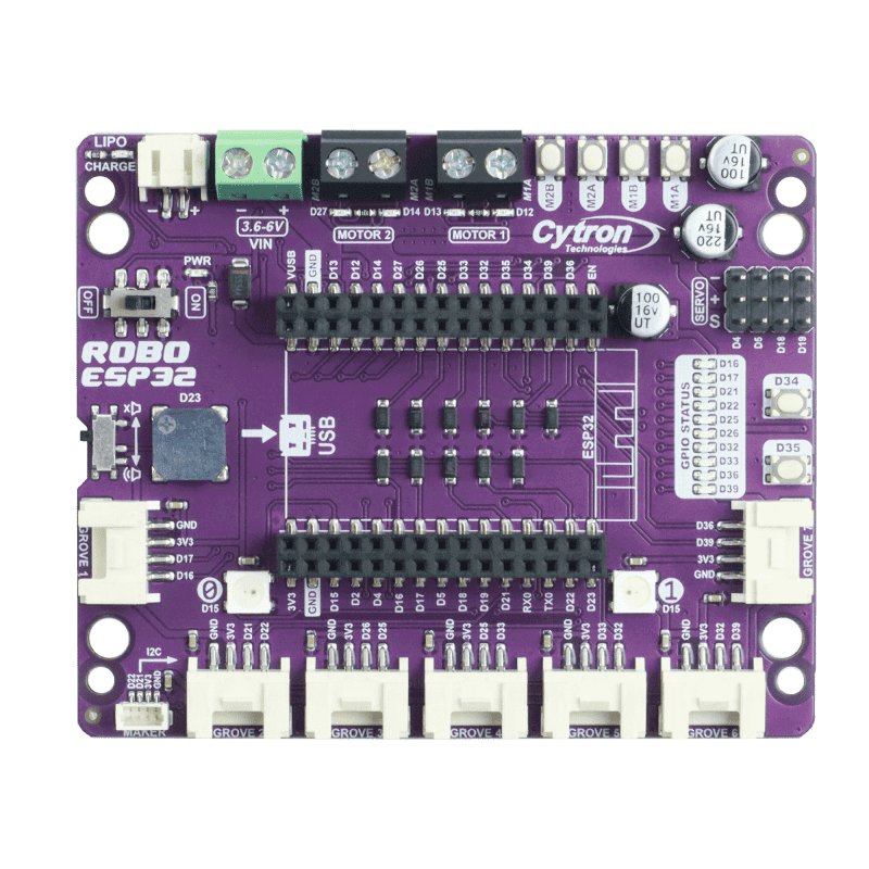
The ESP32-Robo Expansion Board by Cytron is a versatile add-on board designed to enhance the functionality of the ESP32 microcontroller. It provides a wide range of interfaces and connectivity options tailored for robotics and IoT applications. This expansion board integrates motor drivers, sensor ports, and communication interfaces, making it an ideal choice for building smart robots, automation systems, and connected devices.
Explore Projects Built with ESP32-Robo Expansion Board


Explore Projects Built with ESP32-Robo Expansion Board
Common Applications and Use Cases
- Robotics projects requiring motor control and sensor integration
- IoT systems with multiple communication protocols
- Automation systems for home or industrial use
- Educational projects for learning embedded systems and robotics
- Prototyping smart devices with motorized components
Technical Specifications
Key Technical Details
- Microcontroller Compatibility: ESP32
- Motor Driver: Dual-channel DC motor driver (up to 2A per channel)
- Input Voltage: 6V to 12V DC
- Communication Interfaces: UART, I2C, SPI
- Sensor Ports: 4x analog/digital input ports
- Power Output: 5V and 3.3V regulated outputs for external modules
- Dimensions: 90mm x 70mm
- Weight: 50g
Pin Configuration and Descriptions
The ESP32-Robo Expansion Board features multiple pin headers and connectors. Below is a detailed description of the key pins and ports:
Motor Driver Pins
| Pin Name | Description |
|---|---|
| M1A, M1B | Motor 1 terminals for forward/reverse |
| M2A, M2B | Motor 2 terminals for forward/reverse |
| VM | Motor power supply input (6V-12V) |
| GND | Ground connection for motor power |
Sensor Ports
| Pin Name | Description |
|---|---|
| S1, S2, S3, S4 | Sensor input ports (analog/digital) |
| VCC | 5V power output for sensors |
| GND | Ground connection for sensors |
Communication Ports
| Pin Name | Description |
|---|---|
| TX, RX | UART communication pins |
| SDA, SCL | I2C communication pins |
| MOSI, MISO, SCK | SPI communication pins |
Power and Miscellaneous Pins
| Pin Name | Description |
|---|---|
| 5V, 3.3V | Regulated power outputs for peripherals |
| GND | Ground connection |
| EN | Enable pin for ESP32 |
| BOOT | Boot mode selection pin |
Usage Instructions
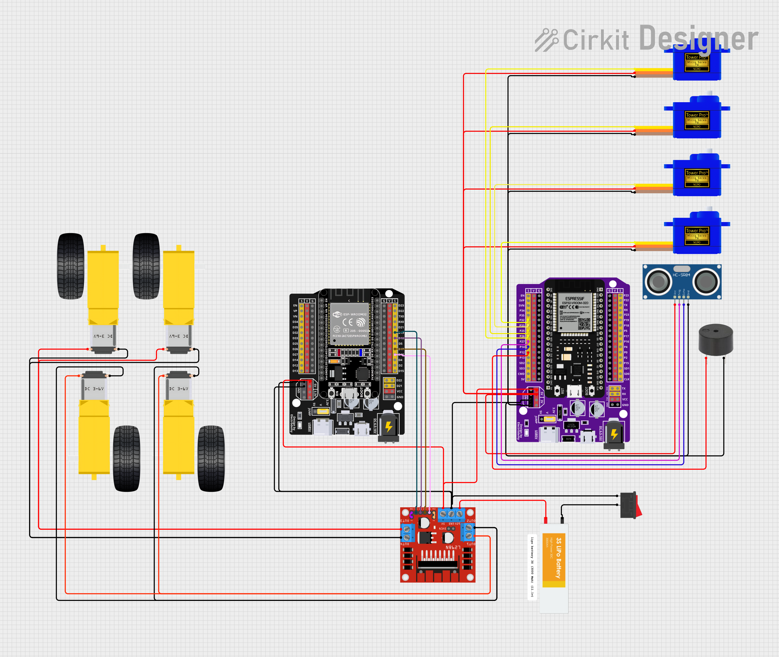
How to Use the Component in a Circuit
Powering the Board:
- Connect a DC power supply (6V-12V) to the VM and GND terminals.
- Ensure the power supply can provide sufficient current for the motors and peripherals.
Connecting Motors:
- Attach the motor wires to the M1A/M1B and M2A/M2B terminals.
- Use the onboard motor driver to control motor speed and direction.
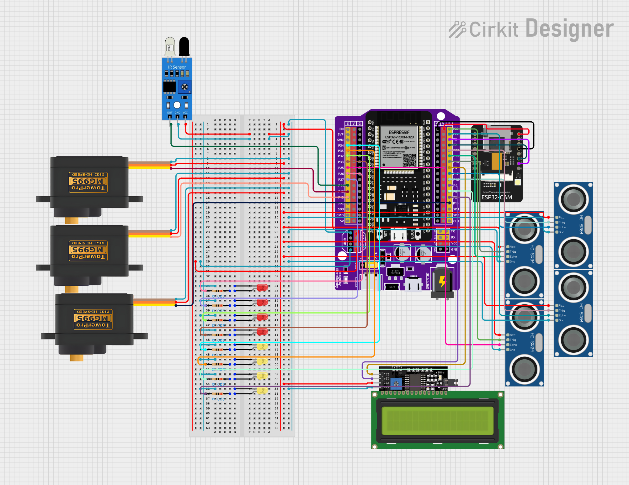
Connecting Sensors:
- Plug sensors into the S1-S4 ports.
- Use the VCC and GND pins to power the sensors.
Programming the ESP32:
- Connect the ESP32 to your computer via USB.
- Use the Arduino IDE or other compatible software to upload code.
Using Communication Interfaces:
- Connect external devices to the UART, I2C, or SPI pins as needed.
- Configure the ESP32 to communicate with these devices in your code.
Important Considerations and Best Practices
- Always check the voltage and current ratings of connected motors and sensors to avoid damage.
- Use proper heat dissipation methods if the motor driver operates at high currents.
- Ensure the ESP32 firmware is compatible with the expansion board's features.
- Avoid short circuits by carefully connecting wires and components.
Example Code for Arduino UNO
Below is an example code snippet to control a motor connected to the ESP32-Robo Expansion Board:
// Example code to control a motor using the ESP32-Robo Expansion Board
// Ensure the motor is connected to M1A and M1B terminals

#define M1A 25  // Define pin for Motor 1 terminal A
#define M1B 26  // Define pin for Motor 1 terminal B

void setup() {
  pinMode(M1A, OUTPUT);  // Set M1A as output
  pinMode(M1B, OUTPUT);  // Set M1B as output
}

void loop() {
  // Rotate motor forward
  digitalWrite(M1A, HIGH);  // Set M1A high
  digitalWrite(M1B, LOW);   // Set M1B low
  delay(2000);              // Run motor for 2 seconds

  // Rotate motor backward
  digitalWrite(M1A, LOW);   // Set M1A low
  digitalWrite(M1B, HIGH);  // Set M1B high
  delay(2000);              // Run motor for 2 seconds

  // Stop motor
  digitalWrite(M1A, LOW);   // Set M1A low
  digitalWrite(M1B, LOW);   // Set M1B low
  delay(1000);              // Wait for 1 second
}
Troubleshooting and FAQs
Common Issues and Solutions
Motors Not Running:
- Cause: Insufficient power supply or incorrect wiring.
- Solution: Verify the power supply voltage and current. Check motor connections.
ESP32 Not Responding:
- Cause: Incorrect firmware or loose connections.
- Solution: Reflash the ESP32 firmware and ensure all connections are secure.
Sensors Not Detecting Properly:
- Cause: Incorrect sensor wiring or incompatible sensor.
- Solution: Verify sensor connections and compatibility with the ESP32.
Overheating Motor Driver:
- Cause: Excessive current draw from motors.
- Solution: Use motors within the rated current limit and add a heatsink if needed.
FAQs
Can I use this board with other microcontrollers?
Yes, but the pinout and firmware must be adapted for compatibility.What is the maximum motor current supported?
The motor driver supports up to 2A per channel.Can I power the ESP32 directly from the board?
Yes, the board provides regulated 5V and 3.3V outputs for the ESP32.Is the board compatible with servo motors?
Yes, servo motors can be connected to the sensor ports with proper PWM control.
This documentation provides a comprehensive guide to using the ESP32-Robo Expansion Board effectively. For further assistance, refer to the manufacturer's resources or community forums.