How to Use DC-DC 12V/24V to 5V 15A Converter 75W Step Down: Examples, Pinouts, and Specs
Introduction
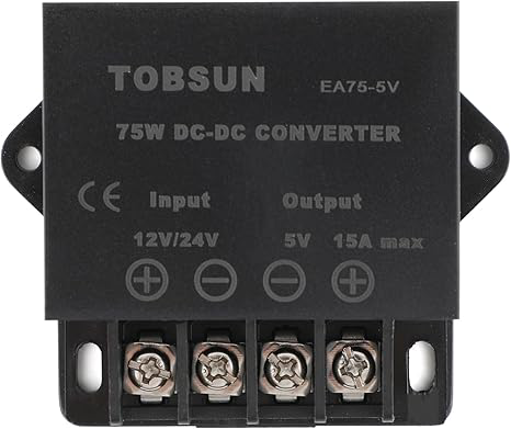
The Tobsun DC-DC 12V/24V to 5V 15A Converter is a high-efficiency step-down power converter designed to provide a stable 5V output from a 12V or 24V DC input. With a maximum output current of 15A and a power rating of 75W, this converter is ideal for powering a wide range of electronic devices, including microcontrollers, sensors, communication modules, and USB-powered devices.
Explore Projects Built with DC-DC 12V/24V to 5V 15A Converter 75W Step Down


Explore Projects Built with DC-DC 12V/24V to 5V 15A Converter 75W Step Down
Common Applications and Use Cases
- Powering USB devices such as smartphones, tablets, and Raspberry Pi boards.
- Supplying power to automotive electronics from a 12V or 24V vehicle battery.
- Providing a stable 5V output for industrial control systems.
- Supporting LED lighting systems and other low-voltage devices.
Technical Specifications
The following table outlines the key technical specifications of the Tobsun DC-DC 12V/24V to 5V 15A Converter:
| Parameter | Specification |
|---|---|
| Input Voltage Range | 8V to 40V DC |
| Output Voltage | 5V DC ± 0.2V |
| Maximum Output Current | 15A |
| Output Power | 75W |
| Efficiency | Up to 96% |
| Ripple and Noise | ≤ 50mV |
| Operating Temperature | -40°C to +80°C |
| Protection Features | Overcurrent, Overvoltage, Overheat, Short Circuit |
| Dimensions | 74mm x 74mm x 32mm |
| Weight | Approximately 150g |
Pin Configuration and Descriptions
The converter has four connection terminals for input and output. The pin configuration is as follows:
| Pin | Label | Description |
|---|---|---|
| 1 | VIN+ | Positive input voltage (12V or 24V DC) |
| 2 | VIN- | Negative input voltage (Ground) |
| 3 | VOUT+ | Positive output voltage (5V DC) |
| 4 | VOUT- | Negative output voltage (Ground) |
Usage Instructions
How to Use the Component in a Circuit
Connect the Input Voltage:
- Connect the positive terminal of your 12V or 24V DC power source to the
VIN+pin. - Connect the negative terminal of your power source to the
VIN-pin.
- Connect the positive terminal of your 12V or 24V DC power source to the
Connect the Output Load:
- Connect the positive terminal of your load (e.g., a 5V device) to the
VOUT+pin. - Connect the negative terminal of your load to the
VOUT-pin.
- Connect the positive terminal of your load (e.g., a 5V device) to the
Verify Connections:
- Double-check all connections to ensure proper polarity and secure wiring.
Power On:
- Turn on the input power source. The converter will automatically regulate the input voltage to provide a stable 5V output.
Important Considerations and Best Practices
- Ensure that the input voltage is within the specified range (8V to 40V DC) to avoid damaging the converter.
- Do not exceed the maximum output current of 15A to prevent overheating or triggering the overcurrent protection.
- Use appropriately rated wires and connectors to handle the high current output.
- Mount the converter in a well-ventilated area to allow proper heat dissipation, especially under high load conditions.
- If using the converter in an automotive environment, consider adding a fuse on the input side for additional protection.
Example: Using the Converter with an Arduino UNO
The Tobsun DC-DC converter can be used to power an Arduino UNO from a 12V car battery. Below is an example wiring diagram and Arduino code:
Wiring Diagram
- Connect the car battery's positive terminal to
VIN+and the negative terminal toVIN-. - Connect the
VOUT+pin to the Arduino UNO's 5V pin. - Connect the
VOUT-pin to the Arduino UNO's GND pin.
Arduino Code Example
// Example code to blink an LED on pin 13 of the Arduino UNO
// Ensure the Arduino is powered via the 5V output of the DC-DC converter

void setup() {
  pinMode(13, OUTPUT); // Set pin 13 as an output pin
}

void loop() {
  digitalWrite(13, HIGH); // Turn the LED on
  delay(1000);            // Wait for 1 second
  digitalWrite(13, LOW);  // Turn the LED off
  delay(1000);            // Wait for 1 second
}
Troubleshooting and FAQs
Common Issues and Solutions
No Output Voltage:
- Cause: Incorrect wiring or insufficient input voltage.
- Solution: Verify that the input voltage is within the 8V to 40V range and check all connections.
Overheating:
- Cause: Excessive load or poor ventilation.
- Solution: Reduce the load to stay within the 15A limit and ensure proper airflow around the converter.
Output Voltage Fluctuations:
- Cause: Input voltage instability or excessive ripple.
- Solution: Use a stable DC power source and consider adding input/output capacitors for additional filtering.
Short Circuit Protection Triggered:
- Cause: Output terminals are shorted.
- Solution: Disconnect the power source, fix the short circuit, and reconnect.
FAQs
Q1: Can this converter be used to charge USB devices?
A1: Yes, the converter provides a stable 5V output suitable for charging USB devices. However, ensure the connected devices do not exceed the 15A current limit.
Q2: Is the converter waterproof?
A2: No, the converter is not waterproof. It should be used in a dry environment or enclosed in a waterproof housing if used outdoors.
Q3: Can I use this converter with a 48V input?
A3: No, the maximum input voltage is 40V. Using a 48V input may damage the converter.
Q4: Does the converter require an external heatsink?
A4: The converter has built-in thermal protection and a heat-dissipating design. However, for continuous high-current applications, additional cooling may be beneficial.