Cirkit Designer Logo
Cirkit Designer
Your all-in-one circuit design IDE
Home / 
Component Documentation

How to Use Adafruit DS3502: Examples, Pinouts, and Specs

Image of Adafruit DS3502
Cirkit Designer LogoDesign with Adafruit DS3502 in Cirkit Designer

Introduction

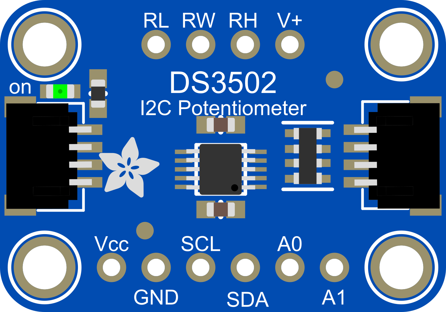
The Adafruit DS3502 is a digital potentiometer, or "digipot," which provides a programmable resistance value across its two terminals. This component is ideal for applications requiring precise control of voltage, current, or signal amplitude. Common use cases include adjusting the brightness of LEDs, controlling the gain of an amplifier, or fine-tuning sensor inputs.

Explore Projects Built with Adafruit DS3502

Use Cirkit Designer to design, explore, and prototype these projects online. Some projects support real-time simulation. Click "Open Project" to start designing instantly!
Arduino Mega 2560-Based Multi-Sensor Weather Station with TFT Display and IR Control
Image of aqua2: A project utilizing Adafruit DS3502 in a practical application
This circuit uses an Arduino Mega 2560 to read temperature data from multiple DS18B20 sensors, display the data on an ILI9341 TFT display, and maintain time using an Adafruit DS1307 RTC module. It also receives IR signals using a VS1838B IR receiver and includes an Adafruit MS8607 PHT sensor for additional environmental monitoring.
Cirkit Designer LogoOpen Project in Cirkit Designer
Arduino Mega 2560 and Adafruit DS1841 Battery-Powered Sensor Interface
Image of Capacitance meter: A project utilizing Adafruit DS3502 in a practical application
This circuit is a sensor interface system powered by a 9V battery, featuring an Arduino Mega 2560 microcontroller and an Adafruit DS1841 digital potentiometer. The circuit includes resistors and capacitors for signal conditioning, with the Arduino handling data acquisition and communication via I2C with the DS1841.
Cirkit Designer LogoOpen Project in Cirkit Designer
Arduino-Based Temperature Monitoring System with RGB LED Feedback and I2C LCD Display
Image of wemos custom shield: A project utilizing Adafruit DS3502 in a practical application
This circuit features an Adafruit Proto Shield R3 configured with a DS18B20 temperature sensor, a WS2812 RGB LED matrix, and an LCD I2C display. The microcontroller on the Proto Shield reads the temperature from the DS18B20 sensor and displays it on the LCD. It also controls the LED matrix to show random colors and indicates temperature status with onboard LEDs.
Cirkit Designer LogoOpen Project in Cirkit Designer
ESP32-Based Smart Weather Station with LED Display and Multiple Sensors
Image of Copy of Zegarek: A project utilizing Adafruit DS3502 in a practical application
This circuit is a multi-sensor data acquisition system using an ESP32 microcontroller. It integrates various sensors including a BH1750 light sensor, BMP280 pressure sensor, DS3231 RTC, and DS18B20 temperature sensor, and displays data on a series of MAX7219 8x8 LED matrices. The system is powered via USB and includes a green LED indicator.
Cirkit Designer LogoOpen Project in Cirkit Designer

Explore Projects Built with Adafruit DS3502

Use Cirkit Designer to design, explore, and prototype these projects online. Some projects support real-time simulation. Click "Open Project" to start designing instantly!
Image of aqua2: A project utilizing Adafruit DS3502 in a practical application
Arduino Mega 2560-Based Multi-Sensor Weather Station with TFT Display and IR Control
This circuit uses an Arduino Mega 2560 to read temperature data from multiple DS18B20 sensors, display the data on an ILI9341 TFT display, and maintain time using an Adafruit DS1307 RTC module. It also receives IR signals using a VS1838B IR receiver and includes an Adafruit MS8607 PHT sensor for additional environmental monitoring.
Cirkit Designer LogoOpen Project in Cirkit Designer
Image of Capacitance meter: A project utilizing Adafruit DS3502 in a practical application
Arduino Mega 2560 and Adafruit DS1841 Battery-Powered Sensor Interface
This circuit is a sensor interface system powered by a 9V battery, featuring an Arduino Mega 2560 microcontroller and an Adafruit DS1841 digital potentiometer. The circuit includes resistors and capacitors for signal conditioning, with the Arduino handling data acquisition and communication via I2C with the DS1841.
Cirkit Designer LogoOpen Project in Cirkit Designer
Image of wemos custom shield: A project utilizing Adafruit DS3502 in a practical application
Arduino-Based Temperature Monitoring System with RGB LED Feedback and I2C LCD Display
This circuit features an Adafruit Proto Shield R3 configured with a DS18B20 temperature sensor, a WS2812 RGB LED matrix, and an LCD I2C display. The microcontroller on the Proto Shield reads the temperature from the DS18B20 sensor and displays it on the LCD. It also controls the LED matrix to show random colors and indicates temperature status with onboard LEDs.
Cirkit Designer LogoOpen Project in Cirkit Designer
Image of Copy of Zegarek: A project utilizing Adafruit DS3502 in a practical application
ESP32-Based Smart Weather Station with LED Display and Multiple Sensors
This circuit is a multi-sensor data acquisition system using an ESP32 microcontroller. It integrates various sensors including a BH1750 light sensor, BMP280 pressure sensor, DS3231 RTC, and DS18B20 temperature sensor, and displays data on a series of MAX7219 8x8 LED matrices. The system is powered via USB and includes a green LED indicator.
Cirkit Designer LogoOpen Project in Cirkit Designer

Technical Specifications

Key Features

  • Resistance Range: 10 kΩ
  • Resolution: 256 steps (7-bit resolution)
  • Interface: I²C-compatible serial interface
  • Operating Voltage: 2.7V to 5.5V
  • Temperature Range: -40°C to +85°C
  • Non-volatile memory (EEPROM) stores the last position

Pin Configuration

Pin Number Name Description
1 SCL Serial Clock Line for I²C communication
2 SDA Serial Data Line for I²C communication
3 A0 Address pin for I²C address selection
4 W Wiper terminal, the variable end of the potentiometer
5 L Low terminal, the low end of the potentiometer
6 H High terminal, the high end of the potentiometer
7 VDD Power supply voltage (2.7V to 5.5V)
8 GND Ground

Usage Instructions

Connecting to a Circuit

  1. Connect VDD to your circuit's power supply (2.7V to 5.5V).
  2. Connect GND to the ground of your circuit.
  3. Connect SCL and SDA to the I²C clock and data lines, respectively.
  4. If multiple I²C devices are used, set the A0 pin to the appropriate logic level to determine the device's address.
  5. Connect the W, L, and H pins to your circuit where variable resistance is needed.

Best Practices

  • Ensure that the power supply voltage does not exceed the maximum rating of 5.5V.
  • Use pull-up resistors on the SCL and SDA lines for reliable I²C communication.
  • Avoid applying a voltage to the W, L, or H terminals that exceeds VDD or is lower than GND.
  • When using in an analog circuit, ensure that the signal voltage across the potentiometer does not exceed the power supply voltage.

Example Code for Arduino UNO

#include <Wire.h>

// DS3502 I2C address (depends on A0 pin connection)
const int DS3502_Address = 0x28; 

// Command to set wiper position
const byte WIPER_REG = 0xA9;

void setup() {
  Wire.begin(); // Join I2C bus
  Serial.begin(9600); // Start serial communication for debugging
  setWiperPosition(128); // Set wiper to mid-scale position
}

void loop() {
  // Example: Cycle through all resistance positions
  for (int position = 0; position < 256; position++) {
    setWiperPosition(position);
    delay(10); // Short delay between changes
  }
}

void setWiperPosition(byte position) {
  Wire.beginTransmission(DS3502_Address); // Begin transmission to DS3502
  Wire.write(WIPER_REG); // Point to wiper register
  Wire.write(position); // Set new wiper position
  Wire.endTransmission(); // End transmission

  // Debug output to serial monitor
  Serial.print("Wiper position set to: ");
  Serial.println(position);
}

Troubleshooting and FAQs

Common Issues

  • I²C Communication Failure: Ensure that pull-up resistors are connected to the SCL and SDA lines. Check for correct wiring and that no other device on the I²C bus has a conflicting address.
  • Unexpected Resistance Values: Verify that the wiper position has been correctly set in the software. Ensure that the DS3502 is not exposed to voltages outside its operating range.

FAQs

Q: Can the DS3502 be used with a microcontroller other than Arduino? A: Yes, the DS3502 can be interfaced with any microcontroller that supports I²C communication.

Q: How do I change the I²C address of the DS3502? A: The I²C address can be changed by connecting the A0 pin to either GND or VDD. This provides two possible addresses for the device.

Q: Is the DS3502 capable of handling power applications? A: The DS3502 is designed for low-power applications and should not be used in high-power circuits.

Q: How do I save the wiper position so it's retained after power cycling? A: The DS3502 automatically stores the last wiper position in its non-volatile memory when powered down.

For further assistance, consult the Adafruit DS3502 datasheet or contact technical support.