How to Use lora: Examples, Pinouts, and Specs
Introduction
LoRa (Long Range) is a low-power wide-area network (LPWAN) technology designed for long-range communication between devices. It is widely used in Internet of Things (IoT) applications to transmit small amounts of data over distances of several kilometers. LoRa operates in unlicensed frequency bands, making it a cost-effective solution for applications requiring long-range, low-power communication.
Explore Projects Built with lora


Explore Projects Built with lora
Common Applications and Use Cases
- Smart agriculture (e.g., soil moisture monitoring, livestock tracking)
- Smart cities (e.g., parking sensors, streetlight control)
- Industrial IoT (e.g., predictive maintenance, asset tracking)
- Environmental monitoring (e.g., air quality sensors, weather stations)
- Home automation and security systems
Technical Specifications
Below are the key technical details for a typical LoRa module (e.g., SX1276-based module):
| Parameter | Value |
|---|---|
| Frequency Bands | 433 MHz, 868 MHz, 915 MHz |
| Modulation | LoRa, FSK |
| Sensitivity | Up to -137 dBm |
| Maximum Output Power | +20 dBm |
| Data Rate | 0.3 kbps to 50 kbps |
| Communication Range | Up to 15 km (line of sight) |
| Supply Voltage | 1.8V to 3.7V |
| Current Consumption (Tx) | ~120 mA (at +20 dBm) |
| Current Consumption (Rx) | ~10 mA |
| Operating Temperature | -40°C to +85°C |
Pin Configuration and Descriptions
The following table describes the pinout for a typical LoRa module (e.g., SX1276):
| Pin Name | Pin Number | Description |
|---|---|---|
| GND | 1 | Ground connection |
| VCC | 2 | Power supply (1.8V to 3.7V) |
| SCK | 3 | SPI Clock |
| MISO | 4 | SPI Master In Slave Out |
| MOSI | 5 | SPI Master Out Slave In |
| NSS | 6 | SPI Chip Select |
| DIO0 | 7 | Digital I/O Pin 0 (used for interrupts) |
| DIO1 | 8 | Digital I/O Pin 1 (optional, for advanced use) |
| RESET | 9 | Reset pin (active low) |
| ANT | 10 | Antenna connection |
Usage Instructions
How to Use the Component in a Circuit
- Power Supply: Connect the VCC pin to a regulated power source (1.8V to 3.7V) and the GND pin to ground.
- SPI Communication: Connect the SCK, MISO, MOSI, and NSS pins to the corresponding SPI pins on your microcontroller.
- Antenna: Attach an appropriate antenna to the ANT pin to ensure optimal signal transmission and reception.
- Interrupts: Use the DIO0 pin for interrupt-driven communication. Additional DIO pins can be used for advanced features.
- Reset: Connect the RESET pin to a GPIO pin on your microcontroller for manual or software-controlled resets.
Important Considerations and Best Practices
- Antenna Selection: Use an antenna tuned to the operating frequency (e.g., 868 MHz or 915 MHz) for maximum range and performance.
- Power Supply: Ensure a stable power supply to avoid communication issues.
- Regulatory Compliance: Verify that the frequency band and transmission power comply with local regulations.
- Line of Sight: For maximum range, ensure a clear line of sight between the transmitter and receiver.
- SPI Configuration: Configure the SPI interface on your microcontroller to match the LoRa module's settings (e.g., clock polarity and phase).
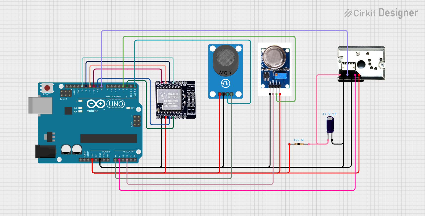
Example: Connecting LoRa to an Arduino UNO
Below is an example of how to connect and program a LoRa module with an Arduino UNO:
Wiring Diagram
| LoRa Pin | Arduino UNO Pin |
|---|---|
| VCC | 3.3V |
| GND | GND |
| SCK | D13 |
| MISO | D12 |
| MOSI | D11 |
| NSS | D10 |
| DIO0 | D2 |
| RESET | D9 |
Arduino Code Example
#include <SPI.h>
#include <LoRa.h> // Include the LoRa library

#define NSS 10    // Chip select pin
#define RESET 9   // Reset pin
#define DIO0 2    // Interrupt pin

void setup() {
  Serial.begin(9600); // Initialize serial communication
  while (!Serial);

  Serial.println("Initializing LoRa module...");

  // Initialize LoRa module
  LoRa.setPins(NSS, RESET, DIO0);
  if (!LoRa.begin(915E6)) { // Set frequency to 915 MHz
    Serial.println("LoRa initialization failed!");
    while (1);
  }

  Serial.println("LoRa initialized successfully!");
}

void loop() {
  Serial.println("Sending packet...");
  LoRa.beginPacket();          // Start a new packet
  LoRa.print("Hello, LoRa!");  // Add data to the packet
  LoRa.endPacket();            // Send the packet

  delay(5000); // Wait 5 seconds before sending the next packet
}
Troubleshooting and FAQs
Common Issues and Solutions
LoRa Module Not Initializing
- Cause: Incorrect wiring or power supply issues.
- Solution: Double-check all connections and ensure the module is receiving the correct voltage.
Poor Communication Range
- Cause: Improper antenna or environmental interference.
- Solution: Use a properly tuned antenna and ensure a clear line of sight between devices.
Data Transmission Fails
- Cause: Mismatched frequency or SPI configuration.
- Solution: Verify that both transmitter and receiver are set to the same frequency and SPI settings.
High Power Consumption
- Cause: Module operating in high-power mode unnecessarily.
- Solution: Use low-power modes when the module is idle.
FAQs
Q: Can I use LoRa for real-time data transmission?
A: LoRa is not ideal for real-time applications due to its low data rate and high latency. It is best suited for periodic data transmission.
Q: What is the maximum range of LoRa?
A: The range can reach up to 15 km in ideal conditions (line of sight). In urban environments, the range may be reduced due to obstacles and interference.
Q: Can multiple LoRa devices communicate with each other?
A: Yes, LoRa supports point-to-point and star network topologies, allowing multiple devices to communicate with a central gateway or with each other.
Q: Is LoRa secure?
A: LoRa supports encryption using AES-128, providing a secure communication channel for IoT applications.