How to Use ESP32 - 38 pins: Examples, Pinouts, and Specs
Introduction
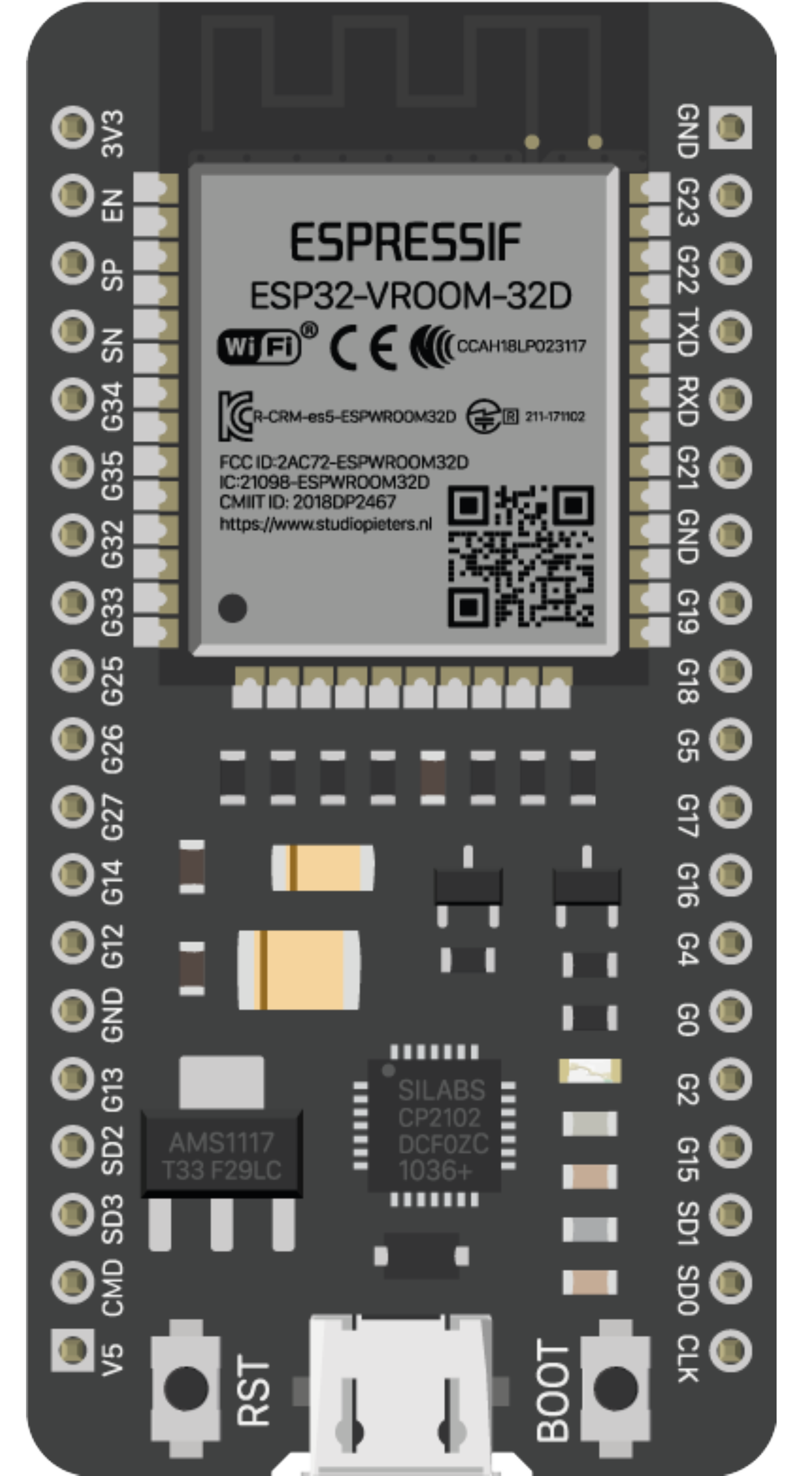
The ESP32 is a versatile system on a chip (SoC) that has been designed for a wide range of Internet of Things (IoT) applications. It integrates Wi-Fi and Bluetooth connectivity, making it ideal for smart home devices, wearable electronics, and various wireless sensors. With its 38 pins, the ESP32 offers a significant number of GPIOs for interfacing with different peripherals and sensors.
Explore Projects Built with ESP32 - 38 pins

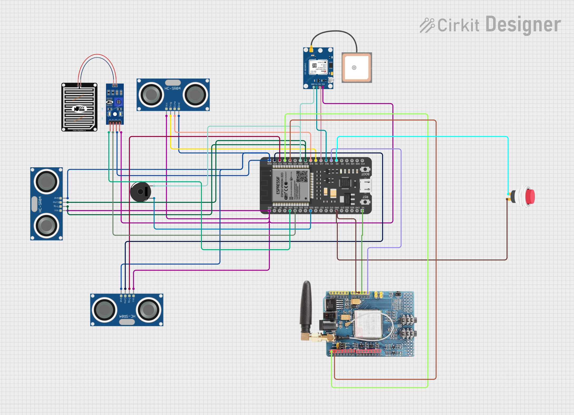

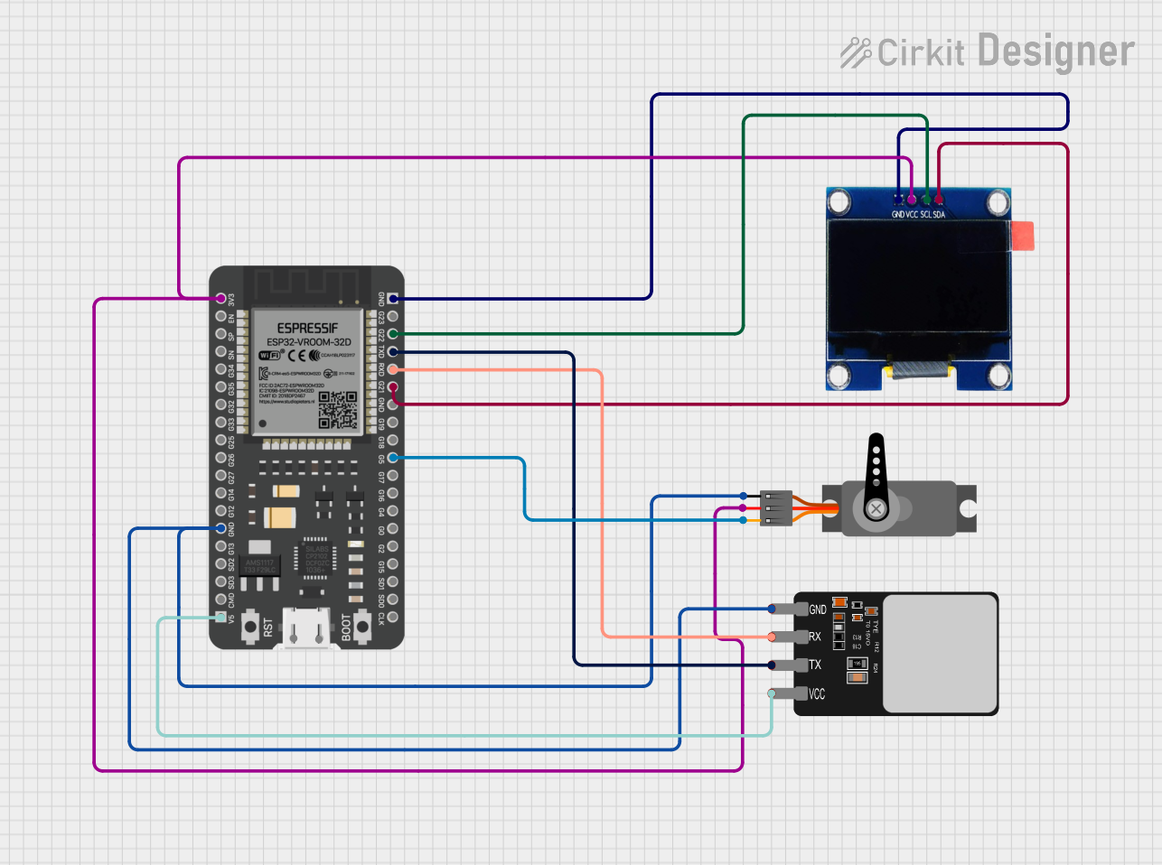
Explore Projects Built with ESP32 - 38 pins
Common Applications and Use Cases
- Smart Home Devices (e.g., smart lights, thermostats)
- Wearable Electronics
- Wireless Sensor Networks
- IoT Prototyping
- Robotics
- DIY Projects
Technical Specifications
Key Technical Details
- Microcontroller: Tensilica Xtensa LX6 dual-core processor
- Operating Voltage: 3.3V
- Input Voltage (recommended): 5V
- Input Voltage (limit): 6-12V
- Digital I/O Pins: 34 (GPIOs)
- Analog Input Pins: 18 (ADC channels)
- Analog Output Pins: 2 (DAC channels)
- Flash Memory: 4MB
- SRAM: 520 KB
- Clock Speed: 240MHz
- Wi-Fi: 802.11 b/g/n
- Bluetooth: v4.2 BR/EDR and BLE
- Temperature Range: -40°C to +125°C
Pin Configuration and Descriptions
| Pin Number | Function | Description |
|---|---|---|
| 1-2 | GND | Ground |
| 3 | 3V3 | 3.3V Power Supply |
| 4-5 | EN | Chip Enable. Active high. |
| 6-7 | VP, VN | ADC0, ADC1 - Sensor Voltage Pins |
| 8-21 | GPIO1 - GPIO14 | General Purpose Input/Output Pins |
| 22-23 | TX0, RX0 | UART0 - Serial Communication Pins |
| 24-25 | GPIO15, GPIO2 | Additional GPIOs |
| 26-27 | TX2, RX2 | UART2 - Additional Serial Communication Pins |
| 28-29 | GPIO4, GPIO0 | Additional GPIOs |
| 30-31 | GPIO16, GPIO17 | Additional GPIOs |
| 32-33 | GPIO5, GPIO18 | Additional GPIOs |
| 34-35 | GPIO19, GPIO21 | Additional GPIOs |
| 36-37 | GPIO3, GPIO1 | Additional GPIOs |
| 38 | VIN | Input Voltage for Battery or External Power |
Usage Instructions
How to Use the Component in a Circuit
Powering the ESP32:
- Connect the 3V3 pin to a 3.3V supply, or VIN to a 5V supply.
- Ensure that the ground pins (GND) are connected to the common ground of your circuit.
Programming the ESP32:
- Use a micro USB cable to connect the ESP32 to your computer.
- Select the appropriate board and port in the Arduino IDE.
Interfacing with Peripherals:
- Connect sensors or actuators to the GPIO pins.
- Use the ADC pins for analog input and DAC pins for analog output.
Important Considerations and Best Practices
- Do not exceed the recommended voltage levels on any pin to prevent damage.
- GPIO pins can be configured as input or output, with various pull-up/pull-down options.
- Some pins have specific functions (e.g., bootstrapping pins) that should be considered during design.
- Ensure that the antenna area is clear of metal components to avoid signal interference.
Example Code for Arduino UNO
#include <WiFi.h>

// Replace with your network credentials
const char* ssid = "your_SSID";
const char* password = "your_PASSWORD";

void setup() {
  Serial.begin(115200);

  // Connect to Wi-Fi
  WiFi.begin(ssid, password);
  while (WiFi.status() != WL_CONNECTED) {
    delay(500);
    Serial.println("Connecting to WiFi...");
  }
  Serial.println("Connected to WiFi");
}

void loop() {
  // Put your main code here, to run repeatedly:
}
Troubleshooting and FAQs
Common Issues
Failure to Connect to Wi-Fi:
- Ensure the SSID and password are correct.
- Check the signal strength and distance from the router.
ESP32 Not Recognized by Computer:
- Install the CP210x USB to UART Bridge VCP Drivers.
- Try a different USB cable or port.
Unexpected Resets or Behavior:
- Check for adequate power supply and stable voltage.
- Ensure that GPIO pins are not overloaded.
Solutions and Tips for Troubleshooting
- Use serial output to debug and track down issues in your code.
- Make sure to have the latest version of the ESP32 board definitions installed in the Arduino IDE.
- Consult the ESP32 datasheet for detailed information on pin functions and limitations.
FAQs
Q: Can I use the ESP32 with a battery? A: Yes, you can power the ESP32 with a battery connected to the VIN pin.
Q: How do I put the ESP32 into deep sleep mode?
A: Use the esp_deep_sleep_start() function after configuring the wake-up source.
Q: Is it possible to use Bluetooth and Wi-Fi simultaneously? A: Yes, the ESP32 can use both Bluetooth and Wi-Fi at the same time, but it may affect performance.
Q: What is the maximum current that GPIO pins can source/sink? A: Each GPIO can source or sink up to 12 mA.
Q: How can I update the firmware on the ESP32? A: Firmware can be updated using the esptool.py utility or through the Arduino IDE.