Cirkit Designer Logo
Cirkit Designer
Your all-in-one circuit design IDE
Home / 
Component Documentation

How to Use vl53l8cx1: Examples, Pinouts, and Specs

Image of vl53l8cx1
Cirkit Designer LogoDesign with vl53l8cx1 in Cirkit Designer

Introduction

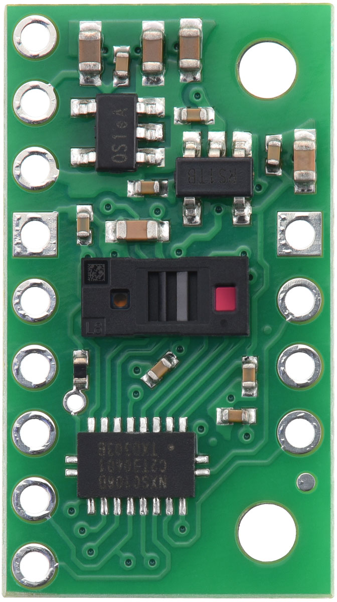
The VL53L8CX-1 is a state-of-the-art, long-distance ranging Time-of-Flight (ToF) sensor, capable of measuring distances with high accuracy by timing the delay of a light signal as it reflects off a target and returns to the sensor. This sensor is particularly well-suited for applications that require quick and accurate distance measurements, such as robotics, user detection, drones, and IoT devices. Its ability to handle multi-target detection makes it versatile for complex scenarios.

Explore Projects Built with vl53l8cx1

Use Cirkit Designer to design, explore, and prototype these projects online. Some projects support real-time simulation. Click "Open Project" to start designing instantly!
Arduino UNO with A9G GSM/GPRS and Dual VL53L1X Distance Sensors
Image of TED CIRCUIT : A project utilizing vl53l8cx1 in a practical application
This circuit features an Arduino UNO microcontroller interfaced with an A9G GSM/GPRS+GPS/BDS module and two VL53L1X time-of-flight distance sensors. The A9G module is connected to the Arduino via serial communication for GPS and GSM functionalities, while both VL53L1X sensors are connected through I2C with shared SDA and SCL lines and individual SHUT pins for selective sensor activation. The Arduino is programmed to control these peripherals, although the specific functionality is not detailed in the provided code.
Cirkit Designer LogoOpen Project in Cirkit Designer
ESP32-S3 Based Smart IoT Distance Sensor with Ethernet Connectivity
Image of ttt: A project utilizing vl53l8cx1 in a practical application
This circuit features an ESP32-S3 microcontroller interfaced with a KY-019 Relay module, a VL53L1X time-of-flight sensor, and a W5500 Ethernet module. The ESP32-S3 controls the relay and communicates with the VL53L1X sensor via I2C, as well as with the network through the Ethernet module. An AC source is converted to DC for powering the components, and a micro USB connection is used to trigger the relay.
Cirkit Designer LogoOpen Project in Cirkit Designer
Battery-Powered ESP32-Controlled Water Valve with Distance Sensing
Image of smart urinal flusher: A project utilizing vl53l8cx1 in a practical application
This circuit features an ESP32 Devkit V1 microcontroller interfaced with a VL53L1X time-of-flight distance sensor and controls a 5V relay module, which in turn operates a water solenoid valve. The ESP32 reads distance measurements from the VL53L1X via I2C (using SDA and SCL lines) and can interrupt (INT) or shut down (SHUT) the sensor. The relay module is actuated by the ESP32 to control the power to the solenoid valve, allowing for automated water flow based on the sensor input or other logic programmed into the ESP32.
Cirkit Designer LogoOpen Project in Cirkit Designer
Cellular-Enabled IoT Device with Real-Time Clock and Power Management
Image of LRCM PHASE 2 BASIC: A project utilizing vl53l8cx1 in a practical application
This circuit features a LilyGo-SIM7000G module for cellular communication and GPS functionality, interfaced with an RTC DS3231 for real-time clock capabilities. It includes voltage sensing through two voltage sensor modules, and uses an 8-channel opto-coupler for isolating different parts of the circuit. Power management is handled by a buck converter connected to a DC power source and batteries, with a fuse for protection and a rocker switch for on/off control. Additionally, there's an LED for indication purposes.
Cirkit Designer LogoOpen Project in Cirkit Designer

Explore Projects Built with vl53l8cx1

Use Cirkit Designer to design, explore, and prototype these projects online. Some projects support real-time simulation. Click "Open Project" to start designing instantly!
Image of TED CIRCUIT : A project utilizing vl53l8cx1 in a practical application
Arduino UNO with A9G GSM/GPRS and Dual VL53L1X Distance Sensors
This circuit features an Arduino UNO microcontroller interfaced with an A9G GSM/GPRS+GPS/BDS module and two VL53L1X time-of-flight distance sensors. The A9G module is connected to the Arduino via serial communication for GPS and GSM functionalities, while both VL53L1X sensors are connected through I2C with shared SDA and SCL lines and individual SHUT pins for selective sensor activation. The Arduino is programmed to control these peripherals, although the specific functionality is not detailed in the provided code.
Cirkit Designer LogoOpen Project in Cirkit Designer
Image of ttt: A project utilizing vl53l8cx1 in a practical application
ESP32-S3 Based Smart IoT Distance Sensor with Ethernet Connectivity
This circuit features an ESP32-S3 microcontroller interfaced with a KY-019 Relay module, a VL53L1X time-of-flight sensor, and a W5500 Ethernet module. The ESP32-S3 controls the relay and communicates with the VL53L1X sensor via I2C, as well as with the network through the Ethernet module. An AC source is converted to DC for powering the components, and a micro USB connection is used to trigger the relay.
Cirkit Designer LogoOpen Project in Cirkit Designer
Image of smart urinal flusher: A project utilizing vl53l8cx1 in a practical application
Battery-Powered ESP32-Controlled Water Valve with Distance Sensing
This circuit features an ESP32 Devkit V1 microcontroller interfaced with a VL53L1X time-of-flight distance sensor and controls a 5V relay module, which in turn operates a water solenoid valve. The ESP32 reads distance measurements from the VL53L1X via I2C (using SDA and SCL lines) and can interrupt (INT) or shut down (SHUT) the sensor. The relay module is actuated by the ESP32 to control the power to the solenoid valve, allowing for automated water flow based on the sensor input or other logic programmed into the ESP32.
Cirkit Designer LogoOpen Project in Cirkit Designer
Image of LRCM PHASE 2 BASIC: A project utilizing vl53l8cx1 in a practical application
Cellular-Enabled IoT Device with Real-Time Clock and Power Management
This circuit features a LilyGo-SIM7000G module for cellular communication and GPS functionality, interfaced with an RTC DS3231 for real-time clock capabilities. It includes voltage sensing through two voltage sensor modules, and uses an 8-channel opto-coupler for isolating different parts of the circuit. Power management is handled by a buck converter connected to a DC power source and batteries, with a fuse for protection and a rocker switch for on/off control. Additionally, there's an LED for indication purposes.
Cirkit Designer LogoOpen Project in Cirkit Designer

Technical Specifications

Key Features

  • Type: Time-of-Flight (ToF) sensor
  • Light Source: 940 nm Vertical Cavity Surface Emitting Laser (VCSEL)
  • Detection Range: Up to 4 meters
  • Resolution: Down to 1 mm
  • Interface: I2C
  • Supply Voltage: 2.6 V to 3.5 V
  • Operating Temperature Range: -20°C to 70°C

Pin Configuration and Descriptions

Pin Number Name Description
1 VDD Power supply (2.6 V to 3.5 V)
2 GND Ground reference for the power supply
3 SDA I2C Data line
4 SCL I2C Clock line
5 GPIO1 Programmable interrupt output
6 XSHUT Active-low shutdown input

Usage Instructions

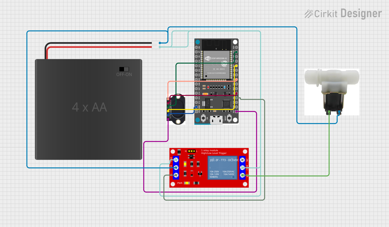
Integration into a Circuit

  1. Power Supply: Connect the VDD pin to a 2.6 V to 3.5 V power source and the GND pin to the ground.
  2. I2C Communication: Connect the SDA and SCL pins to the corresponding I2C data and clock lines on your microcontroller.
  3. Interrupts (Optional): The GPIO1 pin can be used for interrupts. Connect it to an interrupt-capable GPIO pin on your microcontroller if this feature is needed.
  4. Shutdown Control (Optional): The XSHUT pin can be used to put the sensor into a low-power state. Connect it to a GPIO pin on your microcontroller to control this feature.

Best Practices

  • Ensure that the power supply is stable and within the specified voltage range.
  • Use pull-up resistors on the I2C data and clock lines as required by your microcontroller's I2C interface.
  • Avoid placing objects within the minimum detection range when powering up the sensor, as this can affect calibration.
  • Keep the sensor away from direct sunlight and other strong light sources that could interfere with the measurements.

Example Code for Arduino UNO

#include <Wire.h>

// VL53L8CX-1 I2C address (check datasheet for your device's address)
#define SENSOR_ADDRESS 0x29

void setup() {
  Wire.begin(); // Initialize I2C
  Serial.begin(9600); // Start serial communication at 9600 baud rate

  // Sensor initialization code here
  // ...
}

void loop() {
  // Code to trigger measurement and read distance
  // ...

  // Example: Print the measured distance
  Serial.print("Distance: ");
  Serial.print(distance);
  Serial.println(" mm");

  delay(1000); // Wait for 1 second before next measurement
}

Troubleshooting and FAQs

Common Issues

  • No Data from Sensor: Ensure that the sensor is correctly powered and that the I2C connections are secure. Check for proper pull-up resistors on the I2C lines.
  • Inaccurate Measurements: Verify that the sensor is not facing any reflective surfaces or operating in an environment with strong ambient light. Recalibrate if necessary.
  • Intermittent Operation: Check the power supply for stability and the XSHUT pin for unintentional toggling.

FAQs

Q: Can the VL53L8CX-1 sensor measure distances beyond 4 meters? A: The sensor is optimized for distances up to 4 meters. Measurements beyond this range may be less accurate or unreliable.

Q: Is the sensor waterproof? A: No, the VL53L8CX-1 is not inherently waterproof. Additional protection is required for use in moist or wet environments.

Q: How can I reduce power consumption when the sensor is not in use? A: Utilize the XSHUT pin to put the sensor into a low-power state when it is not actively measuring distances.

For further assistance, consult the manufacturer's datasheet and application notes, or contact technical support.