How to Use Rhino MDD20Amp 6V-30V Dual DC Motor Driver (2 Channels): Examples, Pinouts, and Specs
Introduction
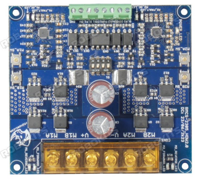
The Rhino MDD20Amp 6V-30V Dual DC Motor Driver is a high-performance motor driver designed to control two DC motors simultaneously. With a current rating of 20 Amps per channel and an operating voltage range of 6V to 30V, this motor driver is ideal for robotics, automation, and other motor control applications. Its robust design ensures reliable operation in demanding environments, making it a popular choice for hobbyists and professionals alike.
Explore Projects Built with Rhino MDD20Amp 6V-30V Dual DC Motor Driver (2 Channels)


Explore Projects Built with Rhino MDD20Amp 6V-30V Dual DC Motor Driver (2 Channels)
Common Applications
- Robotics (e.g., controlling robot wheels or arms)
- Automated conveyor systems
- Electric vehicles and carts
- Industrial automation
- Remote-controlled vehicles and drones
Technical Specifications
Below are the key technical details of the Rhino MDD20Amp Motor Driver:
| Parameter | Specification |
|---|---|
| Operating Voltage Range | 6V to 30V |
| Continuous Current Rating | 20A per channel |
| Peak Current Rating | 50A per channel (for short durations) |
| Number of Channels | 2 (dual motor control) |
| Control Signal Voltage | 3.3V to 5V (logic level compatible) |
| PWM Frequency | Up to 20 kHz |
| Dimensions | 60mm x 55mm x 15mm |
| Weight | 50g |
Pin Configuration and Descriptions
The Rhino MDD20Amp Motor Driver has the following pin configuration:
Input Pins
| Pin Name | Description |
|---|---|
| IN1 | Control signal for Motor 1 (direction or PWM) |
| IN2 | Control signal for Motor 1 (direction or PWM) |
| IN3 | Control signal for Motor 2 (direction or PWM) |
| IN4 | Control signal for Motor 2 (direction or PWM) |
| ENA | Enable pin for Motor 1 (active HIGH) |
| ENB | Enable pin for Motor 2 (active HIGH) |
Power and Motor Output Pins
| Pin Name | Description |
|---|---|
| VCC | Power supply input (6V to 30V) |
| GND | Ground |
| OUT1 | Output terminal for Motor 1 |
| OUT2 | Output terminal for Motor 1 |
| OUT3 | Output terminal for Motor 2 |
| OUT4 | Output terminal for Motor 2 |
Usage Instructions
How to Use the Component in a Circuit
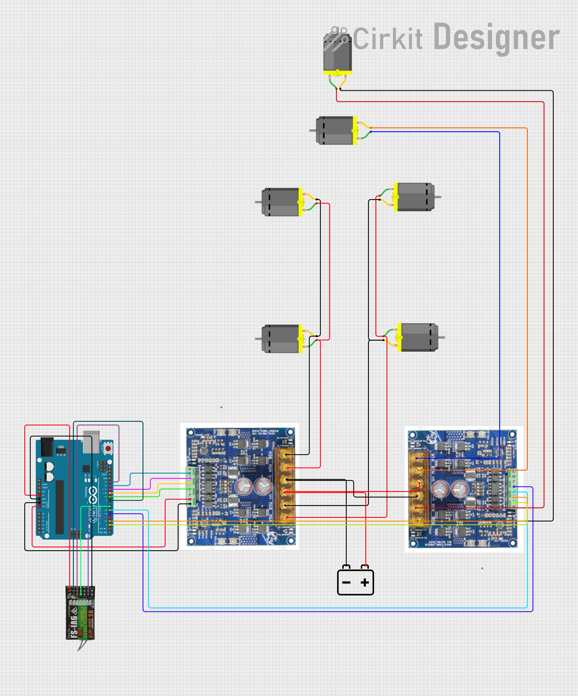
- Power Supply: Connect the VCC pin to a power source within the range of 6V to 30V. Ensure the power supply can handle the current requirements of the motors.
- Motor Connections: Connect the DC motors to the output terminals (OUT1, OUT2 for Motor 1 and OUT3, OUT4 for Motor 2).
- Control Signals: Use a microcontroller (e.g., Arduino UNO) to send control signals to the input pins (IN1, IN2, IN3, IN4) and enable pins (ENA, ENB).
- PWM Control: Use PWM signals on the input pins to control the speed of the motors. The direction can be controlled by toggling the logic levels of the input pins.
Important Considerations
- Ensure the power supply voltage matches the motor's operating voltage.
- Use appropriate heat dissipation methods (e.g., heatsinks) if operating at high currents for extended periods.
- Avoid short circuits between the output terminals to prevent damage to the driver.
- Use decoupling capacitors near the power supply input to reduce noise.
Example Code for Arduino UNO
Below is an example code to control two DC motors using the Rhino MDD20Amp Motor Driver:
// Define motor control pins
const int ENA = 9;  // Enable pin for Motor 1
const int ENB = 10; // Enable pin for Motor 2
const int IN1 = 7;  // Direction pin for Motor 1
const int IN2 = 6;  // Direction pin for Motor 1
const int IN3 = 5;  // Direction pin for Motor 2
const int IN4 = 4;  // Direction pin for Motor 2

void setup() {
  // Set motor control pins as outputs
  pinMode(ENA, OUTPUT);
  pinMode(ENB, OUTPUT);
  pinMode(IN1, OUTPUT);
  pinMode(IN2, OUTPUT);
  pinMode(IN3, OUTPUT);
  pinMode(IN4, OUTPUT);

  // Initialize motors to stop
  digitalWrite(ENA, LOW);
  digitalWrite(ENB, LOW);
  digitalWrite(IN1, LOW);
  digitalWrite(IN2, LOW);
  digitalWrite(IN3, LOW);
  digitalWrite(IN4, LOW);
}

void loop() {
  // Example: Run Motor 1 forward at 50% speed
  analogWrite(ENA, 128); // Set speed (0-255)
  digitalWrite(IN1, HIGH);
  digitalWrite(IN2, LOW);

  // Example: Run Motor 2 backward at 75% speed
  analogWrite(ENB, 192); // Set speed (0-255)
  digitalWrite(IN3, LOW);
  digitalWrite(IN4, HIGH);

  delay(5000); // Run for 5 seconds

  // Stop both motors
  digitalWrite(ENA, LOW);
  digitalWrite(ENB, LOW);
  delay(2000); // Wait for 2 seconds
}
Troubleshooting and FAQs
Common Issues and Solutions
Motors Not Running
- Ensure the power supply is connected and within the specified voltage range.
- Verify that the enable pins (ENA, ENB) are set HIGH.
- Check the connections to the motors and ensure they are secure.
Overheating
- Ensure the motor driver is not exceeding its continuous current rating.
- Use a heatsink or active cooling if operating at high currents.
Erratic Motor Behavior
- Check for loose connections or poor solder joints.
- Add decoupling capacitors to the power supply to reduce noise.
No Response to Control Signals
- Verify that the control signals are within the 3.3V to 5V logic level range.
- Check the microcontroller code for errors.
FAQs
Q: Can I use this motor driver with a 12V battery?
A: Yes, the motor driver supports an operating voltage range of 6V to 30V, so a 12V battery is suitable.
Q: What happens if I exceed the 20A current rating?
A: Exceeding the continuous current rating may cause the motor driver to overheat or fail. Use appropriate current-limiting measures.
Q: Can I control stepper motors with this driver?
A: No, this motor driver is designed for DC motors. Use a dedicated stepper motor driver for stepper motors.
Q: Is it compatible with Raspberry Pi?
A: Yes, the motor driver is compatible with any microcontroller or single-board computer that outputs 3.3V to 5V logic signals.