Cirkit Designer Logo
Cirkit Designer
Your all-in-one circuit design IDE
Home / 
Component Documentation

How to Use Pulse Sensor: Examples, Pinouts, and Specs

Image of Pulse Sensor
Cirkit Designer LogoDesign with Pulse Sensor in Cirkit Designer

Introduction

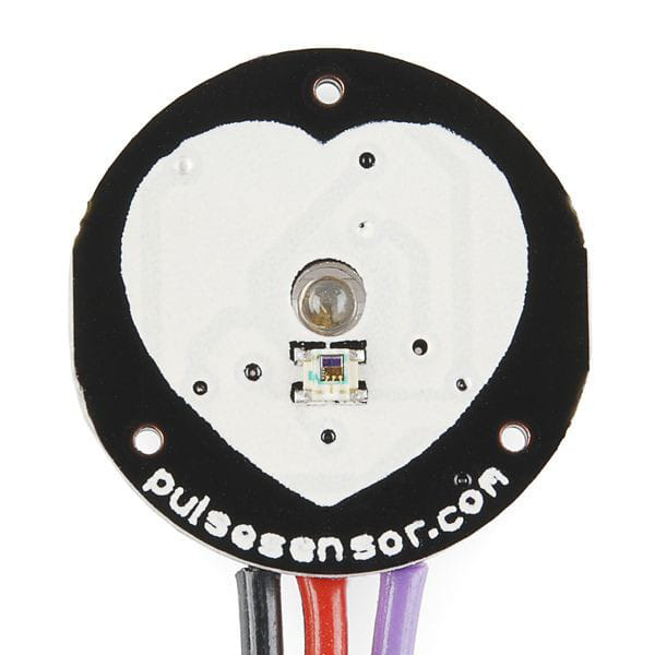
The Pulse Sensor Amped by World Famous Electronics LLC is a compact, plug-and-play heart rate monitoring device. It uses photoplethysmography (PPG) technology to detect blood flow changes in the skin, enabling real-time heart rate measurement. Designed for ease of use, the Pulse Sensor is ideal for applications in fitness tracking, health monitoring, biofeedback systems, and educational projects.

Explore Projects Built with Pulse Sensor

Use Cirkit Designer to design, explore, and prototype these projects online. Some projects support real-time simulation. Click "Open Project" to start designing instantly!
Arduino UNO Based Heart Rate Monitor with OLED Display
Image of Dead Man's switch: A project utilizing Pulse Sensor in a practical application
This circuit is designed to measure heart pulse rate using an Arduino UNO connected to a Heart Pulse Sensor. The sensor's signal is read by the Arduino's analog input A0, and the data is displayed on an OLED screen using I2C communication (SCL and SDA connected to A5 and A4 respectively). The embedded code reads the pulse signal, calculates the beats per minute (BPM), and dynamically displays the BPM value on the OLED.
Cirkit Designer LogoOpen Project in Cirkit Designer
Arduino UNO Based Heart Rate Monitor with I2C LCD Display
Image of PULSE: A project utilizing Pulse Sensor in a practical application
This circuit is designed to monitor heart pulse rate using an Arduino UNO connected to a Heart Pulse Sensor. The pulse signal from the sensor is read by the Arduino on analog pin A0, processed, and the calculated beats per minute (BPM) are displayed on an I2C LCD 16x2 Screen. The entire circuit is powered by a 9V battery, with the Arduino regulating the voltage for the sensor and the LCD screen.
Cirkit Designer LogoOpen Project in Cirkit Designer
Arduino Heartbeat Monitor with I2C LCD Display
Image of Heartbeat Sensor System: A project utilizing Pulse Sensor in a practical application
This circuit is a heartbeat monitoring system using an Arduino UNO, a heart pulse sensor, and a 16x2 I2C LCD. The Arduino reads the pulse sensor data, calculates the beats per minute (BPM), and displays the BPM on the LCD when a button is pressed. An LED also indicates heartbeat detection.
Cirkit Designer LogoOpen Project in Cirkit Designer
Arduino-Based Health Monitoring System with Heart Pulse, Temperature Sensors, and Wi-Fi Notification
Image of detak jantung Blynk: A project utilizing Pulse Sensor in a practical application
This circuit is a health monitoring system that uses an Arduino UNO to read data from a heart pulse sensor, a temperature sensor, and a MAX30102 HR + SpO2 sensor. The data is displayed on an LCD and, if certain thresholds are exceeded, an alert is sent via an ESP8266 WiFi module, with a green LED indicating the alert status.
Cirkit Designer LogoOpen Project in Cirkit Designer

Explore Projects Built with Pulse Sensor

Use Cirkit Designer to design, explore, and prototype these projects online. Some projects support real-time simulation. Click "Open Project" to start designing instantly!
Image of Dead Man's switch: A project utilizing Pulse Sensor in a practical application
Arduino UNO Based Heart Rate Monitor with OLED Display
This circuit is designed to measure heart pulse rate using an Arduino UNO connected to a Heart Pulse Sensor. The sensor's signal is read by the Arduino's analog input A0, and the data is displayed on an OLED screen using I2C communication (SCL and SDA connected to A5 and A4 respectively). The embedded code reads the pulse signal, calculates the beats per minute (BPM), and dynamically displays the BPM value on the OLED.
Cirkit Designer LogoOpen Project in Cirkit Designer
Image of PULSE: A project utilizing Pulse Sensor in a practical application
Arduino UNO Based Heart Rate Monitor with I2C LCD Display
This circuit is designed to monitor heart pulse rate using an Arduino UNO connected to a Heart Pulse Sensor. The pulse signal from the sensor is read by the Arduino on analog pin A0, processed, and the calculated beats per minute (BPM) are displayed on an I2C LCD 16x2 Screen. The entire circuit is powered by a 9V battery, with the Arduino regulating the voltage for the sensor and the LCD screen.
Cirkit Designer LogoOpen Project in Cirkit Designer
Image of Heartbeat Sensor System: A project utilizing Pulse Sensor in a practical application
Arduino Heartbeat Monitor with I2C LCD Display
This circuit is a heartbeat monitoring system using an Arduino UNO, a heart pulse sensor, and a 16x2 I2C LCD. The Arduino reads the pulse sensor data, calculates the beats per minute (BPM), and displays the BPM on the LCD when a button is pressed. An LED also indicates heartbeat detection.
Cirkit Designer LogoOpen Project in Cirkit Designer
Image of detak jantung Blynk: A project utilizing Pulse Sensor in a practical application
Arduino-Based Health Monitoring System with Heart Pulse, Temperature Sensors, and Wi-Fi Notification
This circuit is a health monitoring system that uses an Arduino UNO to read data from a heart pulse sensor, a temperature sensor, and a MAX30102 HR + SpO2 sensor. The data is displayed on an LCD and, if certain thresholds are exceeded, an alert is sent via an ESP8266 WiFi module, with a green LED indicating the alert status.
Cirkit Designer LogoOpen Project in Cirkit Designer

Common Applications

  • Fitness and health monitoring devices
  • Wearable technology
  • Biofeedback systems
  • Educational and research projects
  • Interactive art installations

Technical Specifications

The following table outlines the key technical details of the Pulse Sensor Amped:

Parameter Specification
Manufacturer World Famous Electronics LLC
Part ID Pulse Sensor Amped
Operating Voltage 3.3V to 5V DC
Current Consumption ~4mA
Output Signal Analog (0-1023 for 10-bit ADC)
Sensor Type Photoplethysmography (PPG)
Dimensions 0.625 inches (16mm) diameter
Cable Length ~24 inches (60cm)

Pin Configuration

The Pulse Sensor has a 3-pin interface for easy connection to microcontrollers. The pinout is as follows:

Pin Name Description
1 VCC Power supply input (3.3V to 5V DC)
2 GND Ground connection
3 Signal Analog output signal representing heart rate data

Usage Instructions

Connecting the Pulse Sensor

  1. Power Supply: Connect the VCC pin to a 3.3V or 5V power source, depending on your microcontroller's operating voltage.
  2. Ground: Connect the GND pin to the ground of your circuit.
  3. Signal Output: Connect the Signal pin to an analog input pin on your microcontroller (e.g., A0 on an Arduino UNO).
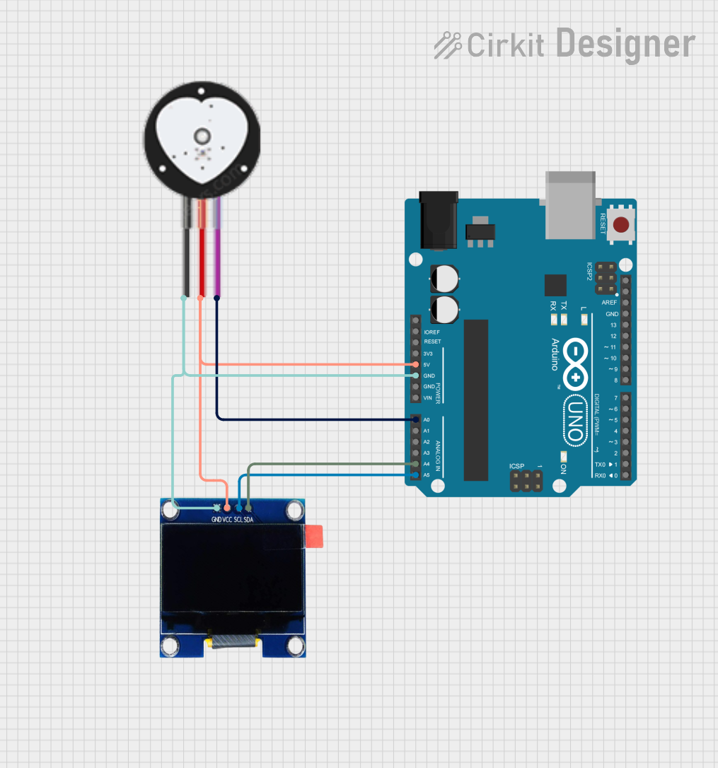
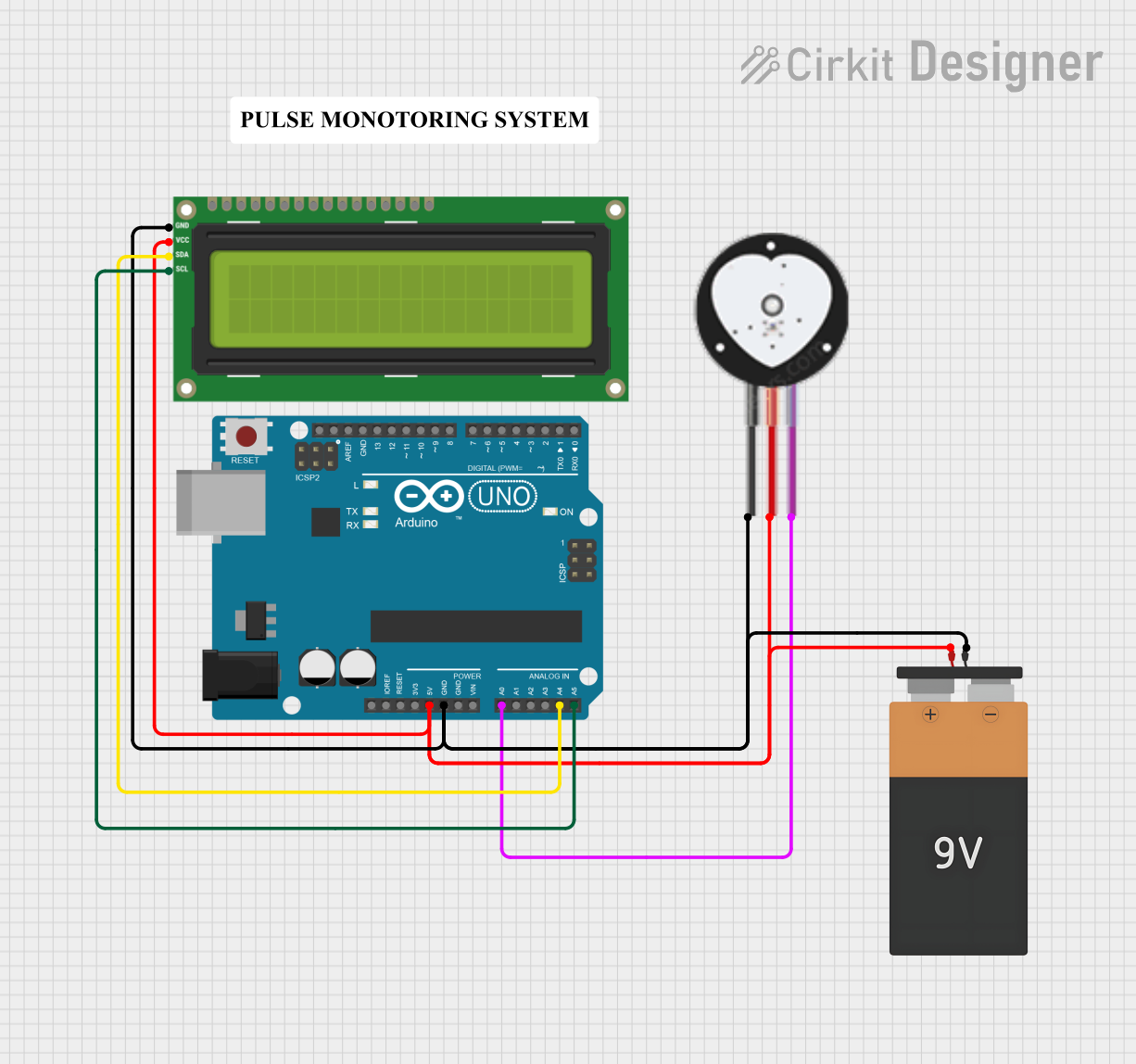
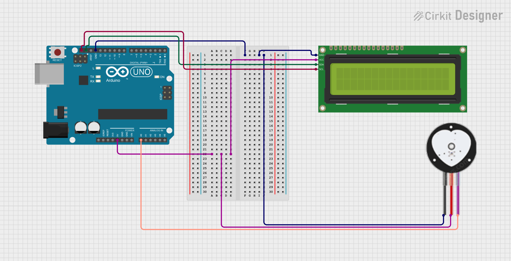
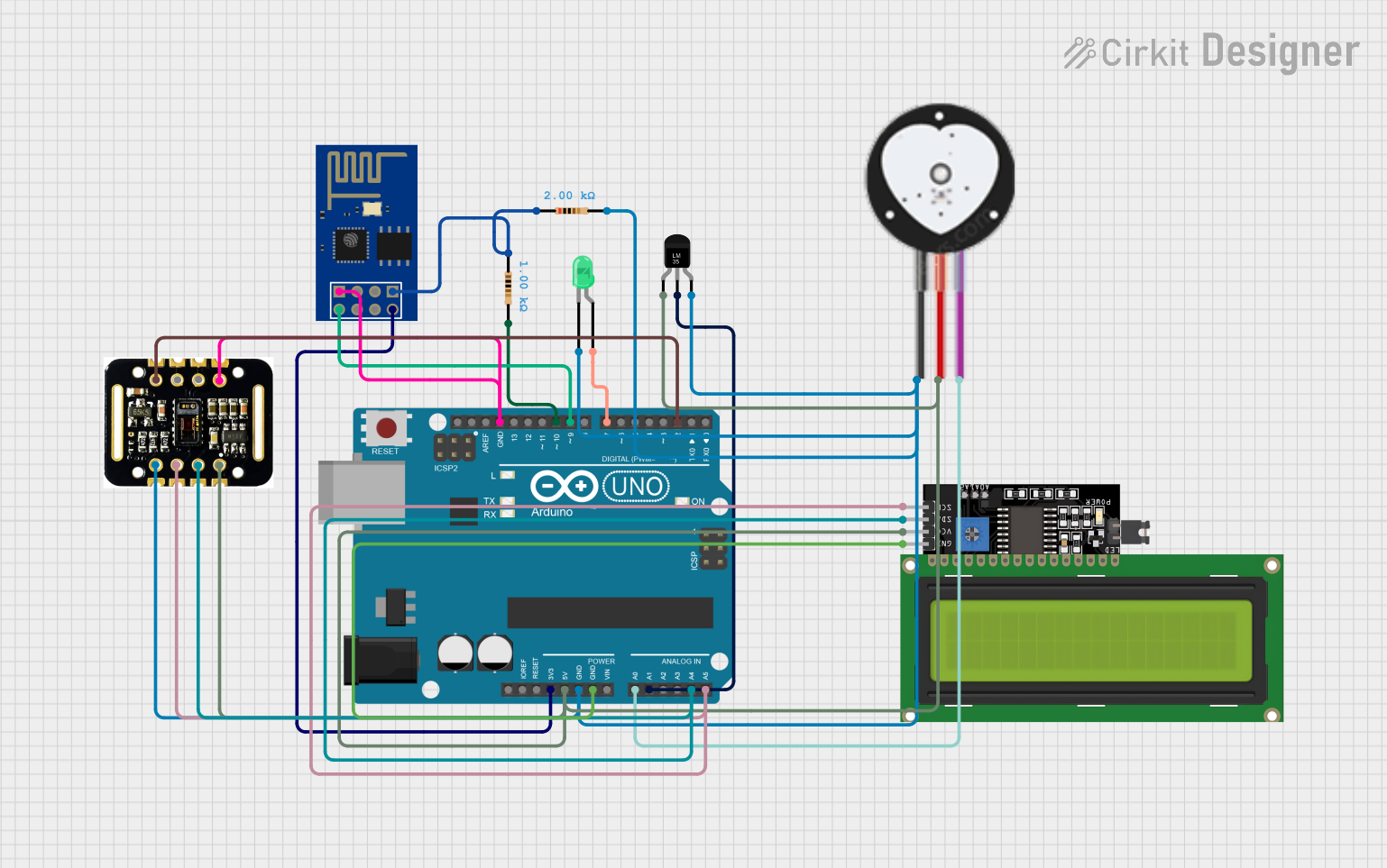
Example Circuit

Below is an example of how to connect the Pulse Sensor to an Arduino UNO:

  • VCC → 5V pin on Arduino
  • GND → GND pin on Arduino
  • Signal → A0 pin on Arduino

Sample Arduino Code

The following code reads the analog signal from the Pulse Sensor and outputs the heart rate data to the Serial Monitor:

// Pulse Sensor Amped - Basic Heart Rate Monitor Example
// Connect Signal pin to A0, VCC to 5V, and GND to GND on Arduino

const int pulsePin = A0;  // Analog pin connected to Pulse Sensor Signal
int pulseValue = 0;       // Variable to store the analog reading

void setup() {
  Serial.begin(9600);  // Initialize Serial Monitor at 9600 baud rate
  pinMode(pulsePin, INPUT);  // Set pulsePin as input
}

void loop() {
  pulseValue = analogRead(pulsePin);  // Read analog value from Pulse Sensor
  Serial.print("Pulse Value: ");      // Print label to Serial Monitor
  Serial.println(pulseValue);         // Print the pulse value
  delay(10);  // Small delay for stable readings
}

Important Considerations

  • Placement: For accurate readings, place the sensor on a fingertip or earlobe. Ensure the sensor is held securely but not too tightly.
  • Ambient Light: Avoid using the sensor in environments with excessive ambient light, as it may interfere with the readings.
  • Signal Filtering: The raw signal may contain noise. Use software filtering or libraries (e.g., PulseSensor Playground) for better results.

Troubleshooting and FAQs

Common Issues and Solutions

  1. No Signal Detected

    • Ensure the sensor is properly connected to the microcontroller.
    • Verify that the VCC pin is receiving the correct voltage (3.3V or 5V).
    • Check the placement of the sensor on the skin.
  2. Inconsistent Readings

    • Minimize movement during measurement to reduce noise.
    • Use a low-pass filter in software to smooth out the signal.
    • Ensure the sensor is not exposed to excessive ambient light.
  3. High Noise in Output

    • Verify that the ground connection is secure.
    • Use shielded cables if the sensor is far from the microcontroller.
    • Place the sensor in a stable environment to reduce interference.

FAQs

Q: Can the Pulse Sensor be used with a 3.3V microcontroller?
A: Yes, the Pulse Sensor operates with both 3.3V and 5V systems.

Q: Is the Pulse Sensor waterproof?
A: No, the Pulse Sensor is not waterproof. Avoid exposing it to water or moisture.

Q: Can I use the Pulse Sensor with a Raspberry Pi?
A: Yes, but since the Raspberry Pi lacks an analog input, you will need an external ADC (Analog-to-Digital Converter) to read the sensor's output.

Q: How do I improve the accuracy of the readings?
A: Use the sensor in a stable, low-light environment and apply software filtering to reduce noise.

This concludes the documentation for the Pulse Sensor Amped. For further assistance, refer to the official resources provided by World Famous Electronics LLC.