How to Use Micro:Bit Breakout: Examples, Pinouts, and Specs
Introduction
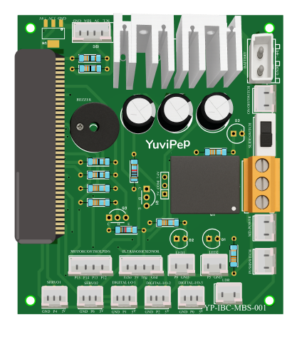
The Micro:Bit Breakout by Yuvipep is a versatile breakout board designed to enhance the functionality of the BBC Micro:Bit microcontroller. It provides easy access to the Micro:Bit's GPIO pins, enabling seamless integration with external sensors, actuators, and modules. Additionally, the breakout board includes features such as a regulated power supply, mounting options, and labeled pin headers for user convenience.
Explore Projects Built with Micro:Bit Breakout
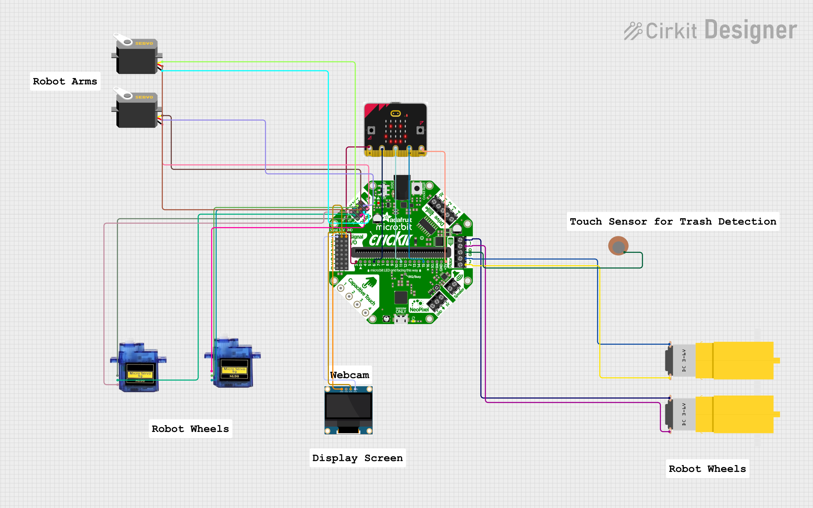


Explore Projects Built with Micro:Bit Breakout
Common Applications and Use Cases
- Prototyping with the BBC Micro:Bit for educational and hobbyist projects.
- Connecting external sensors, motors, and displays to the Micro:Bit.
- Building IoT devices and robotics projects.
- Simplifying circuit assembly for classroom or workshop environments.
Technical Specifications
The Micro:Bit Breakout is designed to interface with the BBC Micro:Bit and provides the following technical features:
Key Technical Details
- Input Voltage: 3.3V to 5V (via Micro:Bit or external power source).
- Output Voltage: 3.3V regulated (for connected peripherals).
- Maximum Current: 500mA (shared across all GPIO pins).
- Pin Headers: 21 labeled GPIO pins (P0–P20) with GND and 3.3V rails.
- Additional Features:
- Dedicated power input terminal for external power sources.
- Mounting holes for secure attachment to enclosures or projects.
- Reverse polarity protection for power input.
Pin Configuration and Descriptions
The breakout board provides access to the Micro:Bit's GPIO pins through labeled headers. Below is the pin configuration:
| Pin Name | Description | Notes |
|---|---|---|
| P0 | General-purpose I/O pin | Supports analog and digital I/O. |
| P1 | General-purpose I/O pin | Supports analog and digital I/O. |
| P2 | General-purpose I/O pin | Supports analog and digital I/O. |
| P3–P20 | General-purpose I/O pins | Digital I/O only. |
| GND | Ground | Common ground for the circuit. |
| 3.3V | Regulated 3.3V output | For powering external components. |
| VIN | External power input | Accepts 3.3V–5V input. |
Usage Instructions
How to Use the Micro:Bit Breakout in a Circuit
- Attach the Micro:Bit: Insert the BBC Micro:Bit into the breakout board's edge connector, ensuring proper alignment.
- Connect Power:
- If using the Micro:Bit's onboard power, no additional power connection is needed.
- For higher power requirements, connect an external 3.3V–5V power source to the VIN and GND terminals.
- Connect Peripherals: Use the labeled GPIO headers to connect sensors, actuators, or other modules. Ensure proper wiring to avoid short circuits.
- Program the Micro:Bit: Write and upload code to the Micro:Bit using the MakeCode editor or Python.
Important Considerations and Best Practices
- Power Supply: Avoid exceeding the 500mA current limit to prevent damage to the breakout board or Micro:Bit.
- Pin Voltage Levels: Ensure connected peripherals operate at 3.3V logic levels to avoid damaging the Micro:Bit.
- Secure Connections: Use jumper wires or DuPont connectors for reliable connections to the GPIO headers.
- Mounting: Use the provided mounting holes to secure the breakout board in your project.
Example Code for Arduino-like Functionality
The following example demonstrates how to use the Micro:Bit Breakout to read an analog sensor connected to pin P0 and control an LED on pin P1.
Import the Micro:Bit module for Python programming
from microbit import *
Main loop
while True: # Read the analog value from pin P0 (e.g., a potentiometer) sensor_value = pin0.read_analog()
# Map the sensor value (0-1023) to an LED brightness level (0-255)
led_brightness = int(sensor_value / 4)

# Set the brightness of an LED connected to pin P1
pin1.write_analog(led_brightness)

# Add a small delay to stabilize readings
sleep(100)
Troubleshooting and FAQs
Common Issues and Solutions
Micro:Bit Not Powering On:
- Cause: Improper power connection or insufficient voltage.
- Solution: Verify the power source and ensure the VIN pin receives 3.3V–5V.
Peripherals Not Responding:
- Cause: Incorrect wiring or incompatible voltage levels.
- Solution: Double-check connections and ensure peripherals operate at 3.3V logic levels.
Overheating:
- Cause: Excessive current draw from connected peripherals.
- Solution: Limit the total current draw to 500mA or use an external power supply.
Micro:Bit Program Not Running:
- Cause: Code errors or improper pin usage.
- Solution: Verify the code and ensure the correct pins are used in the program.
FAQs
Can I use 5V peripherals with the Micro:Bit Breakout?
- No, the Micro:Bit operates at 3.3V logic levels. Use level shifters for 5V peripherals.
What is the maximum current I can draw from the GPIO pins?
- The total current across all GPIO pins should not exceed 500mA.
Can I power the Micro:Bit through the breakout board?
- Yes, you can supply 3.3V–5V to the VIN pin, which will power both the breakout board and the Micro:Bit.
Is the breakout board compatible with all versions of the Micro:Bit?
- Yes, the breakout board is compatible with both Micro:Bit V1 and V2.
By following this documentation, you can effectively use the Micro:Bit Breakout by Yuvipep to expand the capabilities of your BBC Micro:Bit projects.