How to Use USB power: Examples, Pinouts, and Specs
Introduction
A USB power module is an electronic component designed to supply power through a USB connection. It is commonly used to charge electronic devices such as smartphones, tablets, and power USB peripherals like fans, lamps, and small USB gadgets. The module can either be a standalone unit or integrated into a larger system, providing a convenient and standardized power source.
Explore Projects Built with USB power

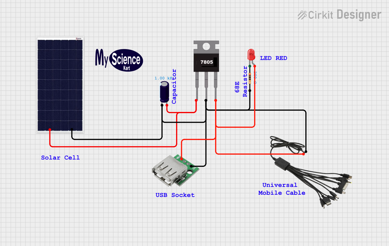

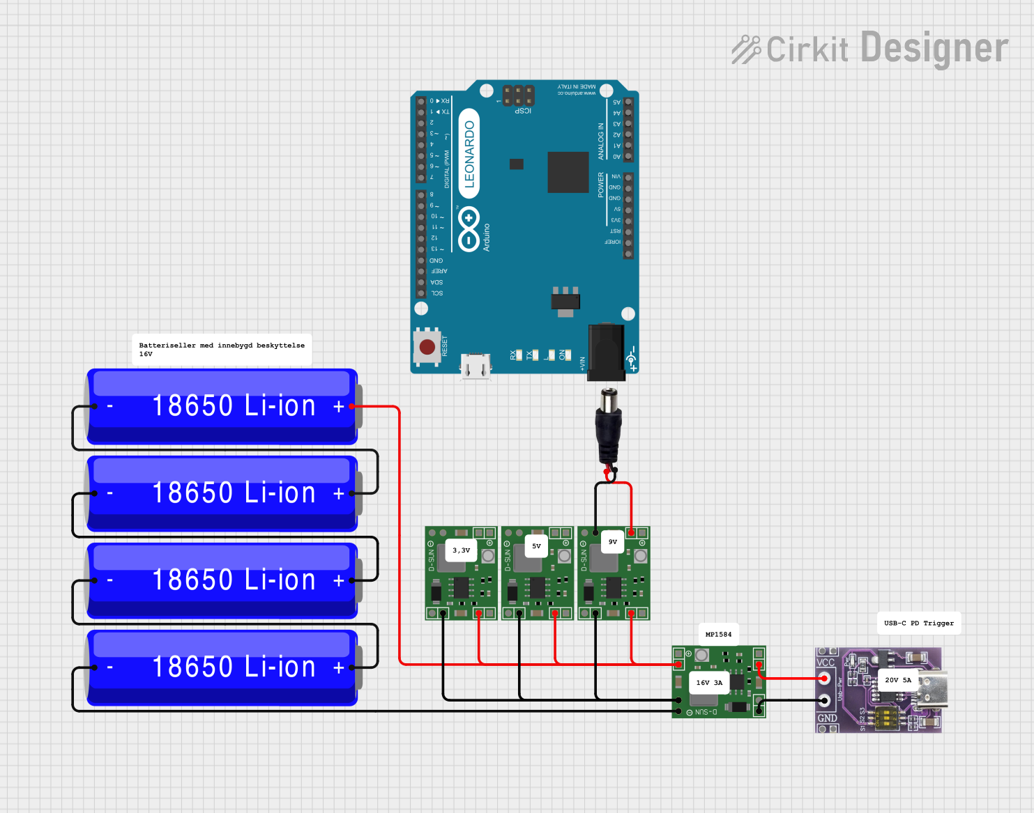
Explore Projects Built with USB power
Common Applications and Use Cases
- Charging portable electronic devices
- Powering USB peripherals
- Providing power for DIY electronics projects
- Serving as a power source for development boards like Arduino
Technical Specifications
Key Technical Details
- Input Voltage: Typically 5V from a standard USB port
- Output Voltage: Usually maintains the 5V standard
- Maximum Output Current: Varies by model (e.g., 500mA, 1A, 2.1A)
- Efficiency: Depends on the conversion technology used
Pin Configuration and Descriptions
| Pin Number | Name | Description |
|---|---|---|
| 1 | VBUS | Provides +5V power |
| 2 | D- | Data- (not used for power-only modules) |
| 3 | D+ | Data+ (not used for power-only modules) |
| 4 | GND | Ground connection |
Usage Instructions
How to Use the Component in a Circuit
- Connect the USB Power Module: Plug the USB power module into a USB port or USB power adapter.
- Verify Output Voltage: Use a multimeter to confirm the output voltage is 5V.
- Connect Your Device: Attach the device or circuit that requires power to the VBUS and GND pins of the module.
Important Considerations and Best Practices
- Current Limitation: Ensure the device's current draw does not exceed the module's maximum output current.
- Heat Dissipation: Some USB power modules may generate heat. Provide adequate ventilation to prevent overheating.
- Cable Quality: Use high-quality USB cables to minimize voltage drop, especially for high-current applications.
- Short Circuit Protection: Always include a fuse or current limiting resistor to protect against short circuits.
Troubleshooting and FAQs
Common Issues Users Might Face
- Insufficient Current: If the device does not function correctly, check if the power module provides enough current.
- Voltage Drop: Long cables or poor connections can cause a voltage drop, leading to device malfunction.
- Overheating: If the module gets too hot, reduce the load or improve cooling.
Solutions and Tips for Troubleshooting
- Check Connections: Ensure all connections are secure and the USB cable is in good condition.
- Measure Voltage and Current: Use a multimeter to measure the output voltage and current to ensure they are within specifications.
- Replace Cable: If you suspect a voltage drop, try a shorter or higher-quality USB cable.
FAQs
Q: Can I use a USB power module to charge any USB device? A: Yes, as long as the device's charging requirements do not exceed the module's output specifications.
Q: Is it safe to leave the USB power module plugged in all the time? A: Generally, it is safe, but it's best to follow the manufacturer's recommendations regarding continuous use.
Q: Can I power an Arduino UNO with a USB power module? A: Yes, an Arduino UNO can be powered via its USB port using a USB power module.
Example Code for Arduino UNO
// This example demonstrates how to power an Arduino UNO using a USB power module.

void setup() {
  // Initialize digital pin LED_BUILTIN as an output.
  pinMode(LED_BUILTIN, OUTPUT);
}

void loop() {
  // Turn the LED on (HIGH is the voltage level)
  digitalWrite(LED_BUILTIN, HIGH);
  // Wait for a second
  delay(1000);
  // Turn the LED off by making the voltage LOW
  digitalWrite(LED_BUILTIN, LOW);
  // Wait for a second
  delay(1000);
}
This code will blink the built-in LED on the Arduino UNO, indicating that it is receiving power from the USB power module. No additional setup is required for the power module itself, as it simply needs to be connected to the Arduino's USB port.