How to Use coding: Examples, Pinouts, and Specs
Introduction
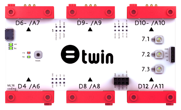
Coding, as defined by Twin's ML16 component, refers to the process of writing instructions for a computer or electronic device to perform specific tasks. These instructions are typically written in programming languages and are essential for creating software, controlling hardware, and automating processes.
Explore Projects Built with coding
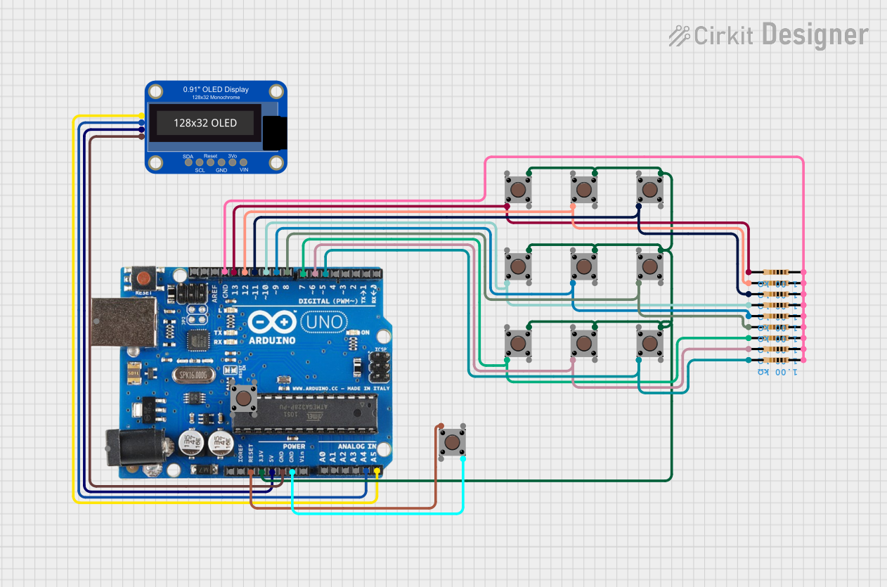
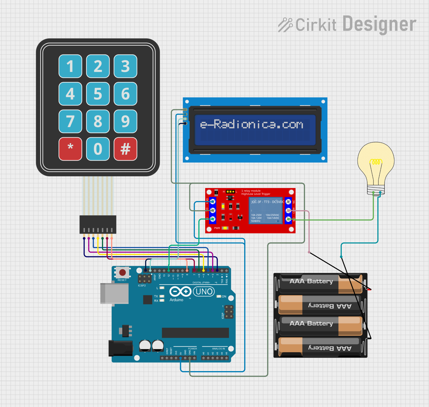
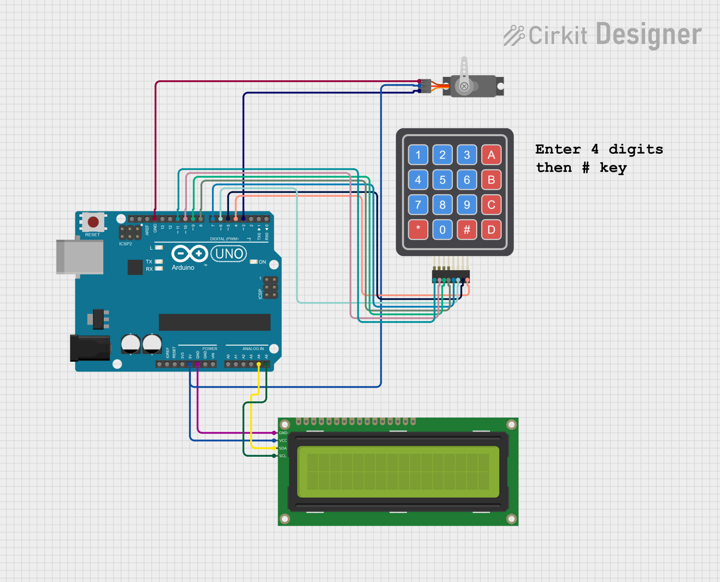
Explore Projects Built with coding
Common Applications and Use Cases
- Embedded Systems: Writing firmware for microcontrollers and processors.
- IoT Devices: Programming sensors, actuators, and communication modules.
- Robotics: Controlling motors, sensors, and decision-making algorithms.
- Prototyping: Rapid development of electronic projects using platforms like Arduino or Raspberry Pi.
- Automation: Creating scripts to automate repetitive tasks in industrial or personal applications.
Technical Specifications
The ML16 component does not have physical pins but serves as a conceptual framework for coding in electronic systems. Below are the key technical details and logical pin mappings for understanding its integration:
Key Technical Details
| Specification | Description |
|---|---|
| Manufacturer | Twin |
| Part ID | ML16 |
| Programming Languages | C, C++, Python, JavaScript, Assembly, and others |
| Supported Platforms | Arduino, Raspberry Pi, ESP32, STM32, and other microcontroller platforms |
| Power Requirements | Dependent on the hardware being programmed |
| Communication Protocols | UART, SPI, I2C, GPIO, and others |
Logical Pin Configuration
While coding itself does not have physical pins, the following table maps common logical "pins" or interfaces used in coding electronic systems:
| Logical Pin/Interface | Description |
|---|---|
| GPIO | General-purpose input/output pins for controlling or reading signals. |
| UART | Serial communication interface for debugging or data transfer. |
| I2C | Communication protocol for interfacing with sensors and peripherals. |
| SPI | High-speed communication protocol for devices like displays or memory. |
| PWM | Pulse-width modulation for controlling motors, LEDs, or other devices. |
Usage Instructions
How to Use Coding in a Circuit
- Select a Platform: Choose a microcontroller or development board (e.g., Arduino UNO, ESP32).
- Write the Code: Use an appropriate programming language and IDE (e.g., Arduino IDE, Python).
- Upload the Code: Transfer the code to the microcontroller using a USB cable or programmer.
- Test the Circuit: Verify the functionality of the circuit and debug if necessary.
Important Considerations and Best Practices
- Understand the Hardware: Familiarize yourself with the datasheets and pin configurations of the components you are programming.
- Use Comments: Write clear comments in your code to explain functionality and logic.
- Optimize Code: Avoid unnecessary loops or delays to improve performance.
- Debugging Tools: Use serial monitors or logic analyzers to troubleshoot issues.
- Power Management: Ensure the power supply is sufficient for all connected components.
Example: Blinking an LED with Arduino UNO
Below is an example of coding an LED to blink using the Arduino UNO:
// This code blinks an LED connected to pin 13 of the Arduino UNO.
// Ensure the LED's longer leg (anode) is connected to pin 13 and the shorter leg
// (cathode) is connected to GND through a resistor (220 ohms recommended).

void setup() {
  pinMode(13, OUTPUT); // Set pin 13 as an output pin
}

void loop() {
  digitalWrite(13, HIGH); // Turn the LED on
  delay(1000);            // Wait for 1 second
  digitalWrite(13, LOW);  // Turn the LED off
  delay(1000);            // Wait for 1 second
}
Troubleshooting and FAQs
Common Issues
Code Does Not Upload:
- Ensure the correct board and port are selected in the IDE.
- Check the USB cable and connection.
Circuit Does Not Work:
- Verify the wiring and connections.
- Check for loose or incorrect connections.
Unexpected Behavior:
- Debug using a serial monitor to print variable values and program flow.
- Ensure the power supply is stable and sufficient.
Solutions and Tips for Troubleshooting
- Use Debugging Tools: Serial monitors, oscilloscopes, or multimeters can help identify issues.
- Check for Syntax Errors: Ensure there are no typos or missing semicolons in the code.
- Test in Isolation: Test individual components or sections of the code to isolate the problem.
- Consult Documentation: Refer to the datasheets and manuals of the hardware being used.
By following this documentation, users can effectively utilize coding to program and control electronic systems, leveraging the capabilities of Twin's ML16 framework.