How to Use Buzzer Module: Examples, Pinouts, and Specs
Introduction
The Buzzer Module by Naresh (Part ID: 1) is an electronic sound-producing device that can be used in a variety of applications, from simple alert systems to complex musical interfaces. It is commonly used in alarm clocks, computers, confirmation of user input (like button presses), and many other scenarios where an audible signal is required.
Explore Projects Built with Buzzer Module


Explore Projects Built with Buzzer Module
Technical Specifications
Key Technical Details
- Operating Voltage: 3.3V to 5V
- Current Consumption: 30mA (typical at 5V)
- Sound Output: ≥85dB at 10cm
- Resonant Frequency: 2.5kHz ± 300Hz
- Operating Temperature: -20°C to 70°C
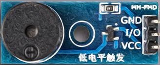
Pin Configuration and Descriptions
| Pin Number | Name | Description |
|---|---|---|
| 1 | VCC | Connect to 3.3V or 5V power supply |
| 2 | GND | Connect to the ground of the circuit |
| 3 | SIG | Signal input, controls the buzzer |
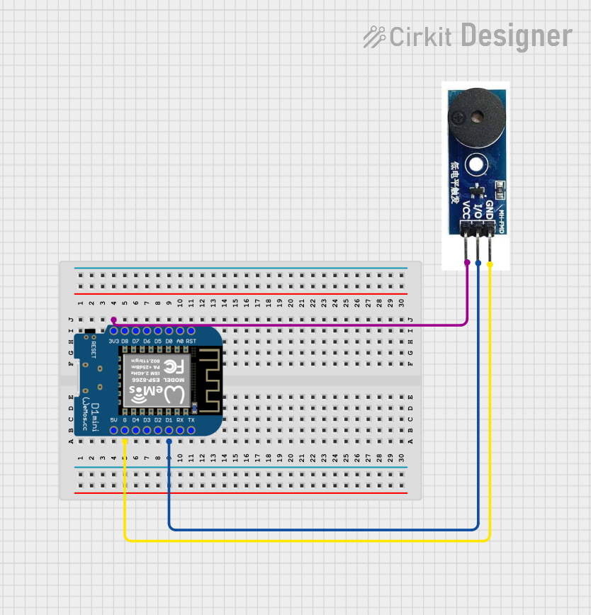
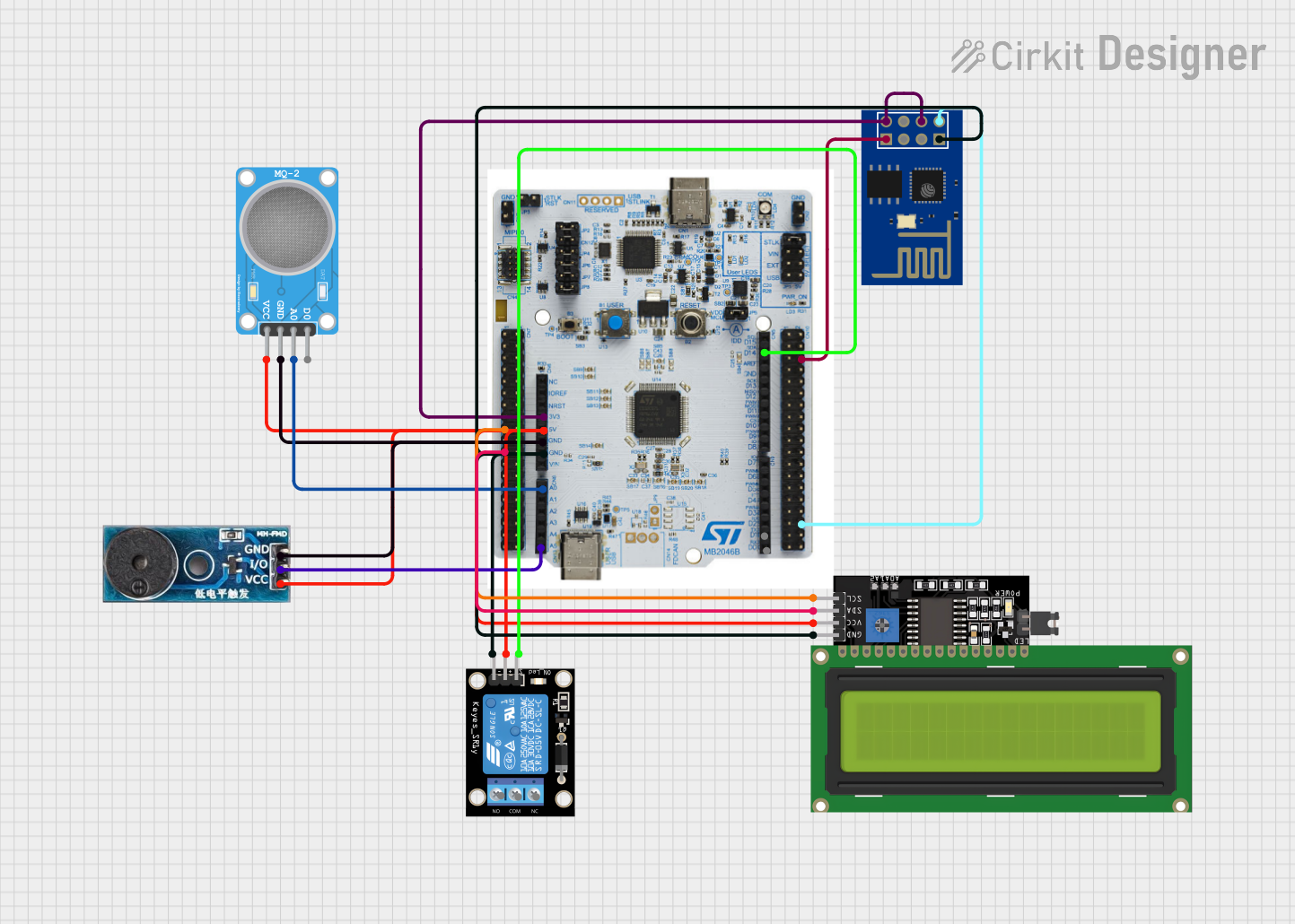
Usage Instructions
Connecting the Buzzer to a Circuit
- Connect the VCC pin to a 3.3V or 5V power supply.
- Connect the GND pin to the ground of your power supply.
- The SIG pin is used to control the buzzer. Connect this to a digital output pin on your microcontroller, such as an Arduino UNO.
Important Considerations and Best Practices
- Ensure that the operating voltage does not exceed the maximum rating to prevent damage.
- The buzzer can be controlled by toggling the SIG pin between HIGH and LOW states.
- Use a current-limiting resistor if you're operating the buzzer at a voltage significantly lower than its rated voltage to prevent excessive current draw.
Example Code for Arduino UNO
// Define the buzzer control pin
#define BUZZER_PIN 8

void setup() {
  // Set the buzzer pin as an output
  pinMode(BUZZER_PIN, OUTPUT);
}

void loop() {
  // Turn on the buzzer
  digitalWrite(BUZZER_PIN, HIGH);
  delay(1000); // Buzzer on for 1 second

  // Turn off the buzzer
  digitalWrite(BUZZER_PIN, LOW);
  delay(1000); // Buzzer off for 1 second
}
This simple example toggles the buzzer on and off every second.
Troubleshooting and FAQs
Common Issues
- Buzzer not sounding: Ensure that the connections are correct and secure. Check that the power supply is within the operating voltage range.
- Sound is very faint: Verify that the buzzer is receiving enough voltage and that the current is not being limited excessively by a resistor.
- Buzzer sounds continuously: Make sure that the signal pin is being toggled correctly in your code.
Solutions and Tips
- If the buzzer is not operating as expected, double-check the wiring against the pin configuration table.
- Use a multimeter to verify that the voltage at the VCC pin is within the specified range.
- Ensure that your microcontroller's code is correctly setting the pin modes and toggling the signal pin.
FAQs
Q: Can I use the buzzer with a 3.3V system? A: Yes, the buzzer can operate at 3.3V, but the sound output may be lower compared to 5V.
Q: Is it possible to control the volume of the buzzer? A: The volume is not directly controllable; it is determined by the voltage and current supplied to the buzzer. However, you can create a perceived volume control by rapidly toggling the signal pin to create a PWM (Pulse Width Modulation) effect.
Q: Can I play different tones with this buzzer? A: This depends on whether the buzzer is an active or passive type. An active buzzer only produces a single tone when powered, while a passive buzzer can be controlled to produce different tones by generating different frequencies with the signal pin.
For further assistance, please contact Naresh customer support.