Cirkit Designer Logo
Cirkit Designer
Your all-in-one circuit design IDE
Home / 
Component Documentation

How to Use ESP32: Examples, Pinouts, and Specs

Image of ESP32
Cirkit Designer LogoDesign with ESP32 in Cirkit Designer

Introduction

The ESP32, manufactured by Espressif, is a low-cost, low-power system on a chip (SoC) with integrated Wi-Fi and Bluetooth capabilities. It is designed for a wide range of applications, including Internet of Things (IoT) devices, smart home systems, wearable electronics, and industrial automation. The ESP32 CH340 variant includes a CH340 USB-to-serial converter, making it easier to program and debug the module via a USB connection.

With its dual-core processor, extensive GPIO options, and support for multiple communication protocols, the ESP32 is a versatile and powerful choice for embedded systems development.

Explore Projects Built with ESP32

Use Cirkit Designer to design, explore, and prototype these projects online. Some projects support real-time simulation. Click "Open Project" to start designing instantly!
ESP32-Based Sensor Monitoring System with OLED Display and E-Stop
Image of MVP_design: A project utilizing ESP32 in a practical application
This circuit features an ESP32 microcontroller that interfaces with a variety of sensors and output devices. It is powered by a Lipo battery through a buck converter, ensuring a stable voltage supply. The ESP32 collects data from a DHT11 temperature and humidity sensor and a vibration sensor, controls a buzzer, and displays information on an OLED screen. An emergency stop (E Stop) is connected for safety purposes, allowing the system to be quickly deactivated.
Cirkit Designer LogoOpen Project in Cirkit Designer
ESP32-Based NTP Clock with DHT22 Temperature Sensor and WS2812 LED Matrix Display
Image of date time and temperature display : A project utilizing ESP32 in a practical application
This circuit features an ESP32 Devkit V1 microcontroller connected to a DHT22 temperature and humidity sensor and an 8x8 WS2812 RGB LED matrix. The ESP32 reads temperature data from the DHT22 sensor and displays the current date, time, and temperature on the LED matrix, with date and time synchronized via NTP (Network Time Protocol). The ESP32 provides power to both the DHT22 and the LED matrix and communicates with the DHT22 via GPIO 4 and with the LED matrix via GPIO 5.
Cirkit Designer LogoOpen Project in Cirkit Designer
ESP32-Based Environmental Monitoring System with Water Flow Sensing
Image of Water: A project utilizing ESP32 in a practical application
This circuit features an ESP32 Devkit V1 microcontroller connected to a DHT22 temperature and humidity sensor and a water flow sensor. The ESP32 reads environmental data from the DHT22 via a digital input pin (D33) and monitors water flow through the water flow sensor connected to another digital input pin (D23). The ESP32 is powered through its VIN pin, and both sensors are powered by the ESP32's 3V3 output, with common ground connections.
Cirkit Designer LogoOpen Project in Cirkit Designer
ESP32-Based Smart Weather Station with Wi-Fi Connectivity
Image of flowchart 3D: A project utilizing ESP32 in a practical application
This circuit features an ESP32 microcontroller interfacing with various sensors and modules, including a DHT22 temperature and humidity sensor, an ESP32 CAM for image capture, an I2C LCD screen for display, a load cell with an HX711 interface for weight measurement, and a buzzer for audio alerts. The ESP32 handles data acquisition, processing, and communication with these peripherals to create a multi-functional monitoring and alert system.
Cirkit Designer LogoOpen Project in Cirkit Designer

Explore Projects Built with ESP32

Use Cirkit Designer to design, explore, and prototype these projects online. Some projects support real-time simulation. Click "Open Project" to start designing instantly!
Image of MVP_design: A project utilizing ESP32 in a practical application
ESP32-Based Sensor Monitoring System with OLED Display and E-Stop
This circuit features an ESP32 microcontroller that interfaces with a variety of sensors and output devices. It is powered by a Lipo battery through a buck converter, ensuring a stable voltage supply. The ESP32 collects data from a DHT11 temperature and humidity sensor and a vibration sensor, controls a buzzer, and displays information on an OLED screen. An emergency stop (E Stop) is connected for safety purposes, allowing the system to be quickly deactivated.
Cirkit Designer LogoOpen Project in Cirkit Designer
Image of date time and temperature display : A project utilizing ESP32 in a practical application
ESP32-Based NTP Clock with DHT22 Temperature Sensor and WS2812 LED Matrix Display
This circuit features an ESP32 Devkit V1 microcontroller connected to a DHT22 temperature and humidity sensor and an 8x8 WS2812 RGB LED matrix. The ESP32 reads temperature data from the DHT22 sensor and displays the current date, time, and temperature on the LED matrix, with date and time synchronized via NTP (Network Time Protocol). The ESP32 provides power to both the DHT22 and the LED matrix and communicates with the DHT22 via GPIO 4 and with the LED matrix via GPIO 5.
Cirkit Designer LogoOpen Project in Cirkit Designer
Image of Water: A project utilizing ESP32 in a practical application
ESP32-Based Environmental Monitoring System with Water Flow Sensing
This circuit features an ESP32 Devkit V1 microcontroller connected to a DHT22 temperature and humidity sensor and a water flow sensor. The ESP32 reads environmental data from the DHT22 via a digital input pin (D33) and monitors water flow through the water flow sensor connected to another digital input pin (D23). The ESP32 is powered through its VIN pin, and both sensors are powered by the ESP32's 3V3 output, with common ground connections.
Cirkit Designer LogoOpen Project in Cirkit Designer
Image of flowchart 3D: A project utilizing ESP32 in a practical application
ESP32-Based Smart Weather Station with Wi-Fi Connectivity
This circuit features an ESP32 microcontroller interfacing with various sensors and modules, including a DHT22 temperature and humidity sensor, an ESP32 CAM for image capture, an I2C LCD screen for display, a load cell with an HX711 interface for weight measurement, and a buzzer for audio alerts. The ESP32 handles data acquisition, processing, and communication with these peripherals to create a multi-functional monitoring and alert system.
Cirkit Designer LogoOpen Project in Cirkit Designer

Common Applications

  • IoT devices and smart home automation
  • Wireless sensor networks
  • Wearable electronics
  • Industrial control systems
  • Robotics and drones
  • Prototyping and educational projects

Technical Specifications

Key Technical Details

Parameter Value
Manufacturer Espressif
Part ID ESP32 CH340
Processor Dual-core Xtensa® 32-bit LX6 microprocessor
Clock Speed Up to 240 MHz
Flash Memory 4 MB (varies by module)
SRAM 520 KB
Wi-Fi 802.11 b/g/n (2.4 GHz)
Bluetooth v4.2 BR/EDR and BLE
Operating Voltage 3.3 V
Input Voltage (via USB) 5 V
GPIO Pins 34 (multipurpose)
ADC Channels 18 (12-bit resolution)
DAC Channels 2
Communication Interfaces UART, SPI, I2C, I2S, CAN, PWM
USB-to-Serial Chip CH340
Power Consumption Ultra-low power modes available
Operating Temperature -40°C to 85°C

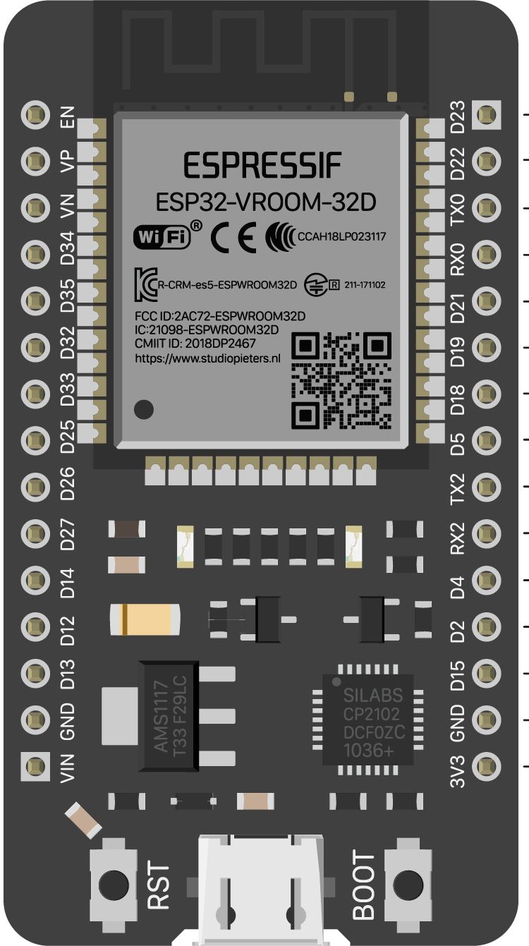
Pin Configuration and Descriptions

The ESP32 has 38 pins in total, with the following key pin assignments:

Pin Number Pin Name Description
1 EN Enable pin (active high)
2 IO0 GPIO0, used for boot mode selection
3 IO1 (TXD0) UART0 Transmit (TX)
4 IO3 (RXD0) UART0 Receive (RX)
5 IO2 GPIO2, general-purpose I/O
6-11 IO12-IO15 GPIO pins, can be used for SPI or PWM
12 GND Ground
13 3V3 3.3 V power output
14-37 IO16-IO39 GPIO pins, ADC, DAC, and other functions
38 VIN Input voltage (5 V via USB or external)

Note: Some pins have specific functions or limitations. Refer to the ESP32 datasheet for detailed pin multiplexing information.

Usage Instructions

How to Use the ESP32 in a Circuit

  1. Powering the ESP32:

    • Connect the ESP32 to a 5 V USB power source or provide 3.3 V directly to the 3V3 pin.
    • Ensure the power supply can provide sufficient current (at least 500 mA).
  2. Programming the ESP32:

    • Install the CH340 driver on your computer to enable USB communication.
    • Use the Arduino IDE or Espressif's ESP-IDF for programming.
    • Select the correct board (e.g., "ESP32 Dev Module") and COM port in the IDE.
  3. Connecting Peripherals:

    • Use GPIO pins for digital input/output, ADC pins for analog input, and DAC pins for analog output.
    • Ensure peripherals operate at 3.3 V logic levels to avoid damaging the ESP32.
  4. Uploading Code:

    • Press and hold the "BOOT" button while uploading code to enter programming mode.
    • Release the button once the upload begins.

Important Considerations and Best Practices

  • Voltage Levels: The ESP32 operates at 3.3 V. Avoid applying 5 V to GPIO pins.
  • Boot Mode: GPIO0 must be pulled low during boot to enter programming mode.
  • Power Supply: Use a stable power source to prevent unexpected resets or malfunctions.
  • Wi-Fi and Bluetooth: Avoid placing the ESP32 near metal objects or enclosures that may interfere with wireless signals.

Example Code for Arduino UNO Integration

The following example demonstrates how to blink an LED connected to GPIO2 of the ESP32:

// Blink an LED connected to GPIO2 on the ESP32
// Ensure the LED's anode is connected to GPIO2 and cathode to GND

#define LED_PIN 2  // GPIO2 is commonly used for onboard LEDs

void setup() {
  pinMode(LED_PIN, OUTPUT);  // Set GPIO2 as an output pin
}

void loop() {
  digitalWrite(LED_PIN, HIGH);  // Turn the LED on
  delay(1000);                  // Wait for 1 second
  digitalWrite(LED_PIN, LOW);   // Turn the LED off
  delay(1000);                  // Wait for 1 second
}

Troubleshooting and FAQs

Common Issues and Solutions

  1. ESP32 Not Detected by Computer:

    • Ensure the CH340 driver is installed correctly.
    • Check the USB cable and port for proper connection.
  2. Code Upload Fails:

    • Verify the correct board and COM port are selected in the IDE.
    • Hold the "BOOT" button during the upload process.
  3. Wi-Fi Connection Issues:

    • Ensure the Wi-Fi credentials are correct.
    • Check for interference or weak signal strength.
  4. Random Resets or Instability:

    • Use a stable power supply with sufficient current capacity.
    • Avoid using GPIO pins that conflict with boot mode.

FAQs

Q: Can the ESP32 operate on battery power?
A: Yes, the ESP32 can be powered by a LiPo battery or other 3.3 V sources. Use a voltage regulator if necessary.

Q: How do I reset the ESP32?
A: Press the "EN" button to reset the ESP32.

Q: Can I use the ESP32 with 5 V logic devices?
A: No, the ESP32 operates at 3.3 V logic levels. Use a level shifter for compatibility with 5 V devices.

Q: What is the maximum range of the ESP32's Wi-Fi?
A: The range depends on environmental factors but typically extends up to 100 meters in open space.