
How to Use aocoda f722: Examples, Pinouts, and Specs
 Design with aocoda f722 in Cirkit Designer
Introduction
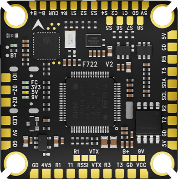
The Aocoda F722, manufactured by Senchtech (Part ID: FC722), is a high-performance flight controller designed specifically for drones. It features advanced processing capabilities, seamless integration with multiple sensors, and support for various flight modes. This makes it an ideal choice for both drone racing enthusiasts and aerial photography professionals. Its robust design and versatile functionality ensure reliable performance in demanding applications.
Explore Projects Built with aocoda f722
 Open Project in Cirkit Designer
 Open Project in Cirkit Designer
 Open Project in Cirkit Designer
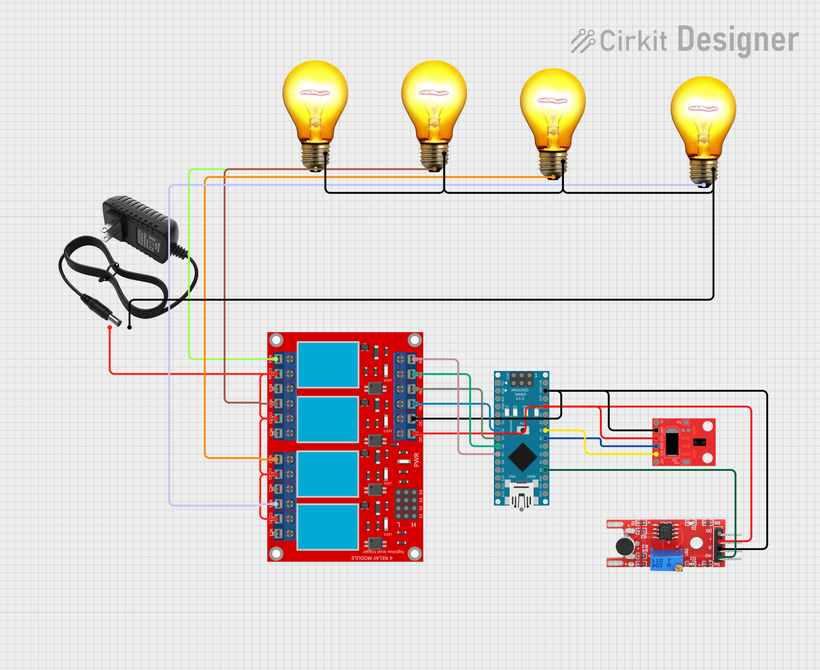 Open Project in Cirkit Designer
Explore Projects Built with aocoda f722
Open Project in Cirkit DesignerOpen Project in Cirkit DesignerOpen Project in Cirkit DesignerOpen Project in Cirkit DesignerCommon Applications and Use Cases
- Racing Drones: High-speed performance with precise control for competitive drone racing.
- Aerial Photography: Stable flight and advanced sensor integration for capturing high-quality images and videos.
- FPV (First-Person View) Drones: Real-time video streaming with low latency for immersive flying experiences.
- Research and Development: Customizable platform for testing and developing drone technologies.
Technical Specifications
Key Technical Details
| Parameter | Specification |
|---|---|
| Processor | STM32F722 MCU (32-bit ARM Cortex-M7) |
| Gyroscope/Accelerometer | MPU6000 (SPI interface) |
| Input Voltage Range | 2S–6S LiPo (7.4V–25.2V) |
| UART Ports | 5 UARTs (configurable for peripherals) |
| I2C Ports | 1 I2C bus for external sensors |
| PWM Outputs | 8 motor outputs (DShot, OneShot, Multishot) |
| Flash Memory | 16MB Blackbox data logging |
| OSD | Integrated Betaflight OSD |
| BEC Output | 5V/2A and 9V/1.5A |
| Dimensions | 36mm x 36mm (30.5mm x 30.5mm mounting holes) |
| Weight | 7 grams |
Pin Configuration and Descriptions
| Pin Name | Description |
|---|---|
| GND | Ground connection for power and signal reference |
| VBAT | Battery voltage input (2S–6S LiPo) |
| 5V | 5V output for powering peripherals |
| 9V | 9V output for powering FPV cameras or other devices |
| M1–M8 | Motor signal outputs (PWM, DShot, OneShot, Multishot) |
| UART1–UART5 | Configurable UART ports for peripherals (e.g., GPS, telemetry, receiver) |
| I2C_SCL | I2C clock line for external sensors |
| I2C_SDA | I2C data line for external sensors |
| RX1–RX5 | UART receive pins for communication |
| TX1–TX5 | UART transmit pins for communication |
| LED_STRIP | Output for programmable LED strips (WS2812 or similar) |
| Buzzer | Connection for an external buzzer |
| RSSI | Analog input for receiver signal strength indication |
| Current | Analog input for current sensor |
| Boot | Bootloader mode activation pin |
Usage Instructions
How to Use the Aocoda F722 in a Circuit
Powering the Flight Controller:
- Connect a 2S–6S LiPo battery to the VBAT pin.
- Ensure the battery voltage is within the supported range (7.4V–25.2V).
- Use the onboard BEC outputs (5V or 9V) to power peripherals like FPV cameras or receivers.
Connecting Motors:
- Connect up to 8 motors to the M1–M8 pins.
- Configure the motor protocol (e.g., DShot, OneShot) in the flight control software.
Peripheral Connections:
- Use the UART ports for connecting GPS modules, telemetry devices, or receivers.
- Connect external sensors (e.g., barometer, magnetometer) to the I2C_SCL and I2C_SDA pins.
Programming and Configuration:
- Use Betaflight Configurator to flash firmware and configure the flight controller.
- Connect the flight controller to your computer via USB and follow the on-screen instructions.
Mounting:
- Secure the flight controller to the drone frame using the 30.5mm x 30.5mm mounting holes.
- Use vibration-dampening materials to minimize interference from motor vibrations.
Important Considerations and Best Practices
- Firmware Compatibility: Ensure the firmware version is compatible with the Aocoda F722. Betaflight is the recommended firmware.
- Heat Management: Avoid overheating by ensuring proper airflow around the flight controller.
- Wiring: Double-check all connections to prevent short circuits or incorrect wiring.
- Calibration: Calibrate the accelerometer and gyroscope before the first flight for accurate performance.
- Blackbox Logging: Use the 16MB flash memory for flight data logging to analyze and improve performance.
Example Code for Arduino UNO Integration
While the Aocoda F722 is not typically used with an Arduino UNO, you can use an Arduino to send commands or read data via UART. Below is an example of how to communicate with the flight controller:
#include <SoftwareSerial.h>

// Define RX and TX pins for SoftwareSerial
SoftwareSerial mySerial(10, 11); // RX = pin 10, TX = pin 11

void setup() {
  // Initialize serial communication
  Serial.begin(9600); // For debugging with the PC
  mySerial.begin(115200); // Communication with Aocoda F722

  Serial.println("Arduino is ready to communicate with Aocoda F722.");
}

void loop() {
  // Send a test command to the flight controller
  mySerial.println("Test Command");

  // Check if data is available from the flight controller
  if (mySerial.available()) {
    String response = mySerial.readString();
    Serial.println("Response from Aocoda F722: " + response);
  }

  delay(1000); // Wait for 1 second before sending the next command
}
Troubleshooting and FAQs
Common Issues and Solutions
Flight Controller Not Powering On:
- Cause: Incorrect wiring or insufficient battery voltage.
- Solution: Verify the battery voltage and ensure proper connection to the VBAT pin.
Motors Not Spinning:
- Cause: Incorrect motor protocol configuration or wiring.
- Solution: Check the motor connections and configure the correct protocol in Betaflight.
No Communication with Betaflight Configurator:
- Cause: USB driver issues or incorrect COM port selection.
- Solution: Install the correct USB drivers and ensure the correct COM port is selected.
Gyroscope/Accelerometer Not Calibrating:
- Cause: Flight controller not placed on a level surface during calibration.
- Solution: Place the flight controller on a flat, stable surface and retry calibration.
OSD Not Displaying on FPV Feed:
- Cause: Incorrect wiring or OSD settings.
- Solution: Verify the FPV camera connection to the 9V output and configure OSD settings in Betaflight.
FAQs
Q: Can I use the Aocoda F722 with a 1S LiPo battery?
A: No, the minimum supported voltage is 7.4V (2S LiPo).Q: What firmware is compatible with the Aocoda F722?
A: The Aocoda F722 is compatible with Betaflight firmware.Q: How do I update the firmware?
A: Use Betaflight Configurator to flash the latest firmware via USB.Q: Can I connect an external barometer?
A: Yes, use the I2C_SCL and I2C_SDA pins to connect external sensors like a barometer.Q: What is the maximum current output of the onboard BEC?
A: The 5V BEC provides up to 2A, and the 9V BEC provides up to 1.5A.
This concludes the documentation for the Aocoda F722 flight controller.