How to Use KY-012 5v buzzer: Examples, Pinouts, and Specs

Introduction
The KY-012 5V Buzzer is a small electronic device that produces sound when an electrical signal is applied. It is commonly used in alarms, notifications, and sound effects in various electronic projects. This passive buzzer requires an external signal to generate sound, making it ideal for applications where specific tones or patterns are needed. Its compact size and ease of use make it a popular choice for hobbyists and professionals alike.
Explore Projects Built with KY-012 5v buzzer

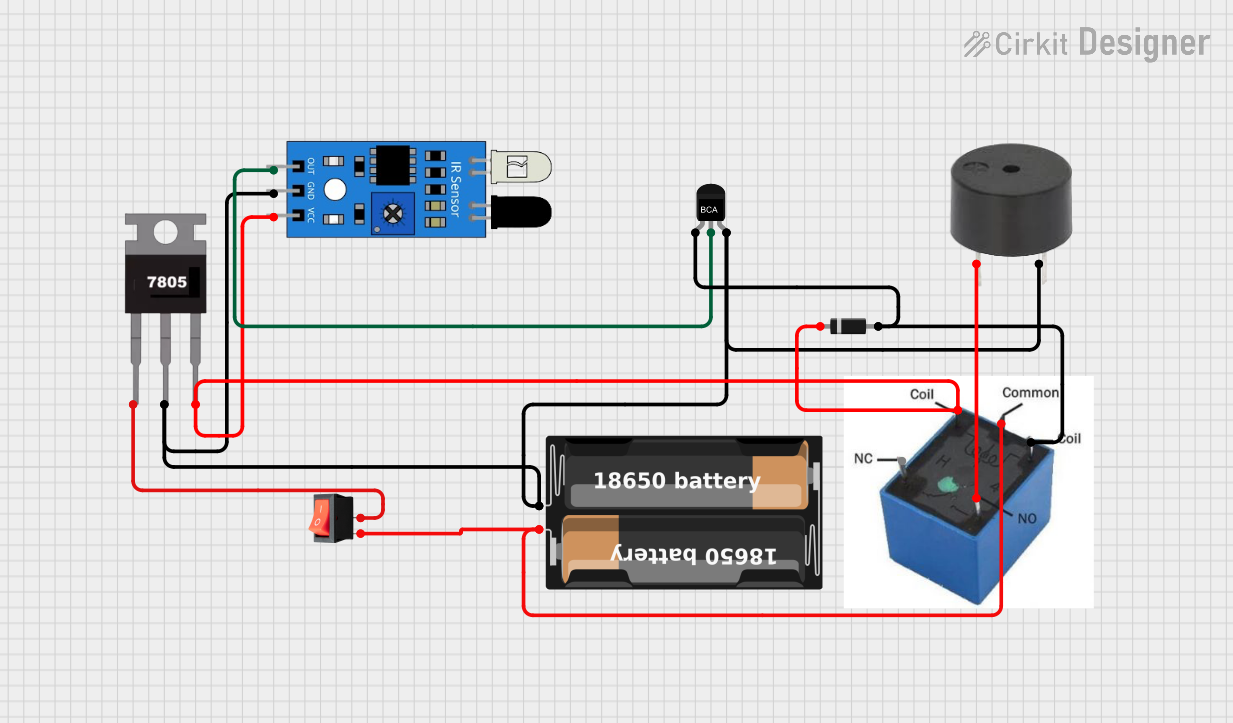
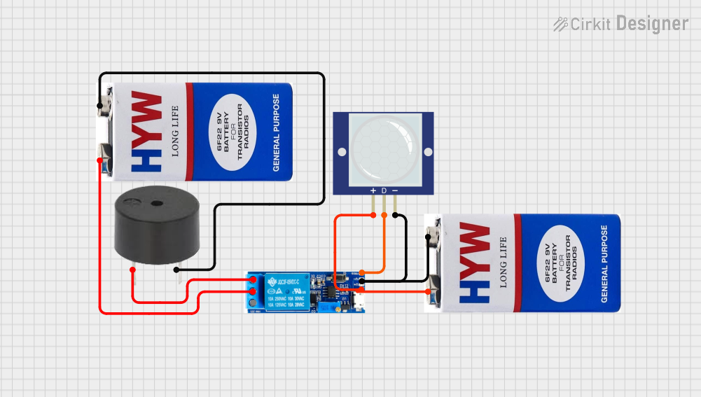
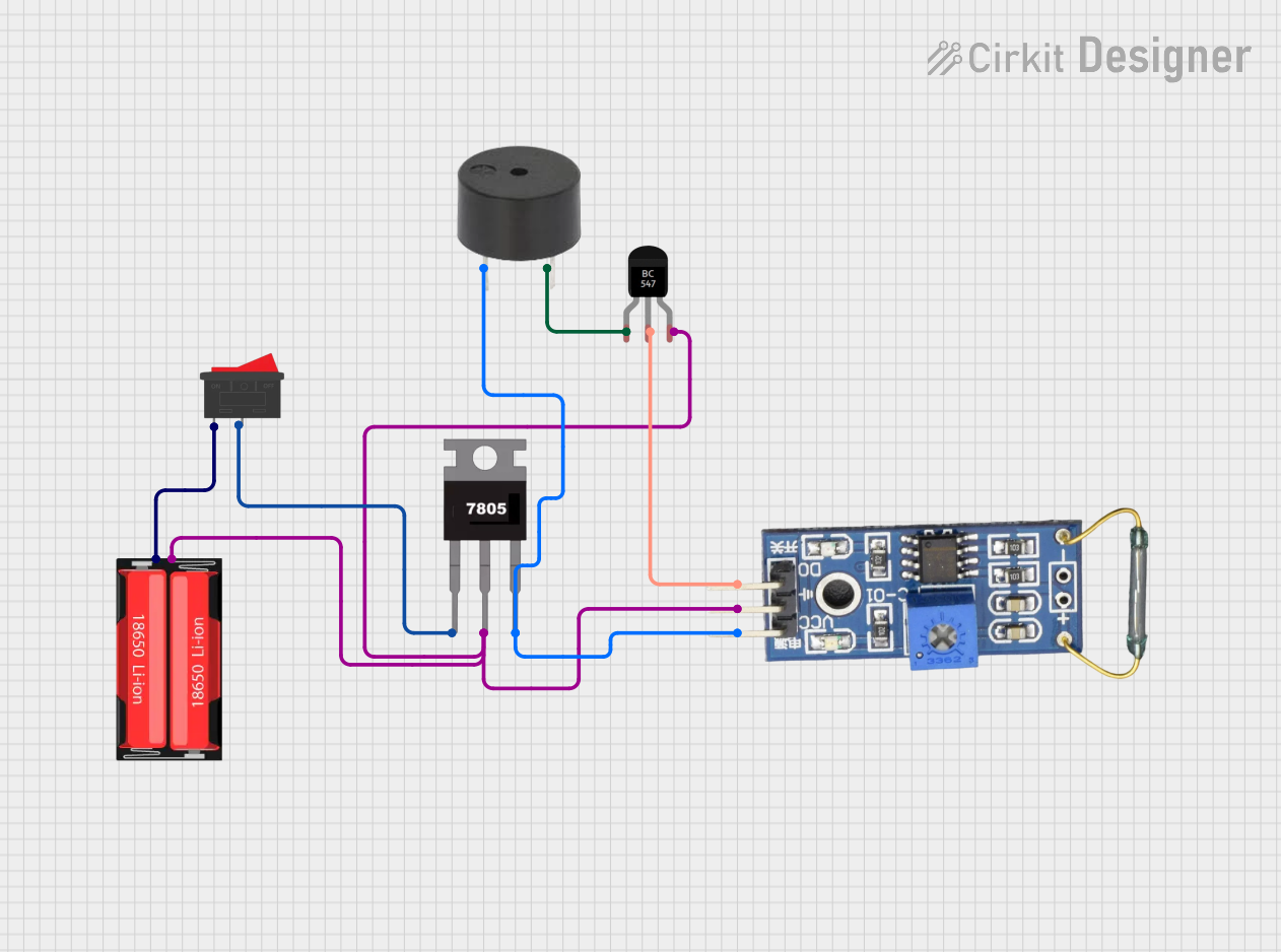
Explore Projects Built with KY-012 5v buzzer
Common Applications:
- Alarm systems
- Notification systems
- Sound effects in electronic projects
- Arduino-based projects
- Educational kits and prototypes
Technical Specifications
Below are the key technical details of the KY-012 5V Buzzer:
| Parameter | Value |
|---|---|
| Operating Voltage | 3.3V - 5V |
| Current Consumption | ≤ 30mA |
| Sound Frequency Range | ~2 kHz |
| Dimensions | 18.5mm x 15mm x 13mm |
| Weight | ~2g |
| Type | Passive Buzzer |
Pin Configuration
The KY-012 module has three pins, but only two are used for operation. The pin configuration is as follows:
| Pin | Label | Description |
|---|---|---|
| 1 | Signal | Input signal pin to control the buzzer |
| 2 | VCC | Power supply pin (3.3V - 5V) |
| 3 | GND | Ground pin |
Note: The "Signal" pin requires a PWM (Pulse Width Modulation) signal to produce sound.
Usage Instructions
How to Use the KY-012 5V Buzzer in a Circuit
Connect the Pins:
- Connect the
VCCpin to a 5V power source (or 3.3V if using a lower voltage system). - Connect the
GNDpin to the ground of your circuit. - Connect the
Signalpin to a microcontroller's PWM-capable pin (e.g., Arduino digital pin with PWM support).
- Connect the
Generate a Signal:
- Use a microcontroller (e.g., Arduino) to send a PWM signal to the
Signalpin. The frequency of the PWM signal determines the tone of the sound produced.
- Use a microcontroller (e.g., Arduino) to send a PWM signal to the
Test the Buzzer:
- Once connected, upload a program to your microcontroller to generate a tone. The buzzer will produce sound based on the input signal.
Important Considerations:
- Signal Type: The KY-012 is a passive buzzer, meaning it requires an external signal to produce sound. It will not work if connected directly to power without a signal.
- Voltage Range: Ensure the operating voltage does not exceed 5V to avoid damaging the component.
- PWM Frequency: Experiment with different PWM frequencies to achieve the desired tone.
Example Code for Arduino UNO
Below is an example of how to use the KY-012 5V Buzzer with an Arduino UNO:
// KY-012 5V Buzzer Example Code
// This code generates a tone on the KY-012 buzzer using Arduino's tone() function.

#define BUZZER_PIN 8  // Define the pin connected to the Signal pin of the buzzer

void setup() {
  pinMode(BUZZER_PIN, OUTPUT);  // Set the buzzer pin as an output
}

void loop() {
  tone(BUZZER_PIN, 2000);  // Generate a 2 kHz tone
  delay(1000);             // Wait for 1 second
  noTone(BUZZER_PIN);      // Stop the tone
  delay(1000);             // Wait for 1 second
}
Note: The
tone()function generates a square wave signal on the specified pin, which is ideal for driving the KY-012 buzzer.
Troubleshooting and FAQs
Common Issues and Solutions:
No Sound from the Buzzer:
- Cause: The
Signalpin is not receiving a proper PWM signal. - Solution: Verify the connection to the microcontroller and ensure the correct pin is used. Check the code to ensure a PWM signal is being generated.
- Cause: The
Low or Distorted Sound:
- Cause: Insufficient voltage or incorrect PWM frequency.
- Solution: Ensure the
VCCpin is connected to a stable 5V power source. Adjust the PWM frequency to achieve a clear tone.
Buzzer Not Responding:
- Cause: Faulty connections or damaged component.
- Solution: Double-check all connections and test the buzzer with a different microcontroller or circuit.
FAQs:
Q: Can I use the KY-012 buzzer without a microcontroller?
A: No, the KY-012 is a passive buzzer and requires an external signal to produce sound. You can use a 555 timer or similar circuit to generate a signal if a microcontroller is not available.Q: What is the difference between a passive and an active buzzer?
A: A passive buzzer requires an external signal to produce sound, while an active buzzer has an internal oscillator and produces sound when powered.Q: Can I use the KY-012 with a 3.3V system?
A: Yes, the KY-012 can operate at 3.3V, but the sound may be quieter compared to 5V operation.
By following this documentation, you can effectively integrate the KY-012 5V Buzzer into your electronic projects and troubleshoot any issues that arise.