How to Use DC-motordriver: Examples, Pinouts, and Specs
Introduction
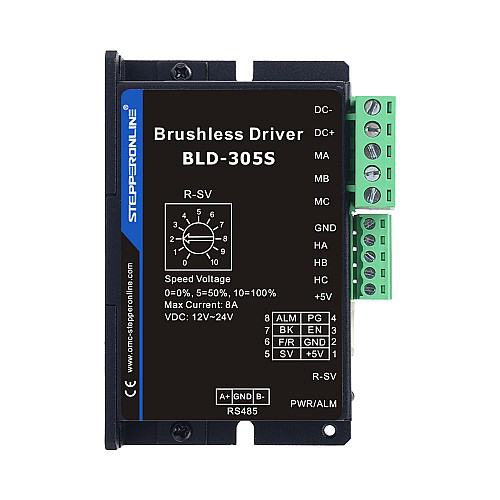
The BLD-405S DC motor driver, manufactured by Stepper Online, is a versatile electronic circuit designed to control the direction and speed of DC motors. By regulating the voltage and current supplied to the motor, this driver ensures precise and efficient motor operation. It is ideal for applications requiring bidirectional motor control, speed adjustment, and smooth operation.
Explore Projects Built with DC-motordriver
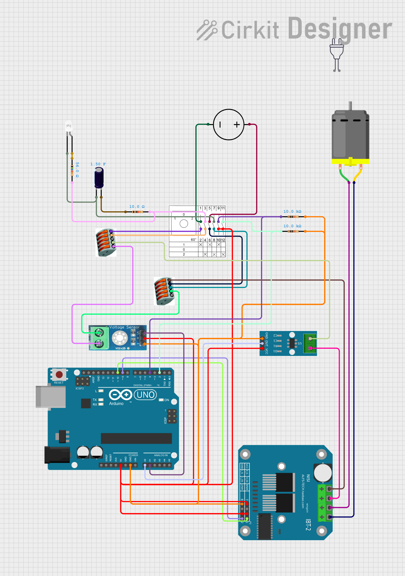
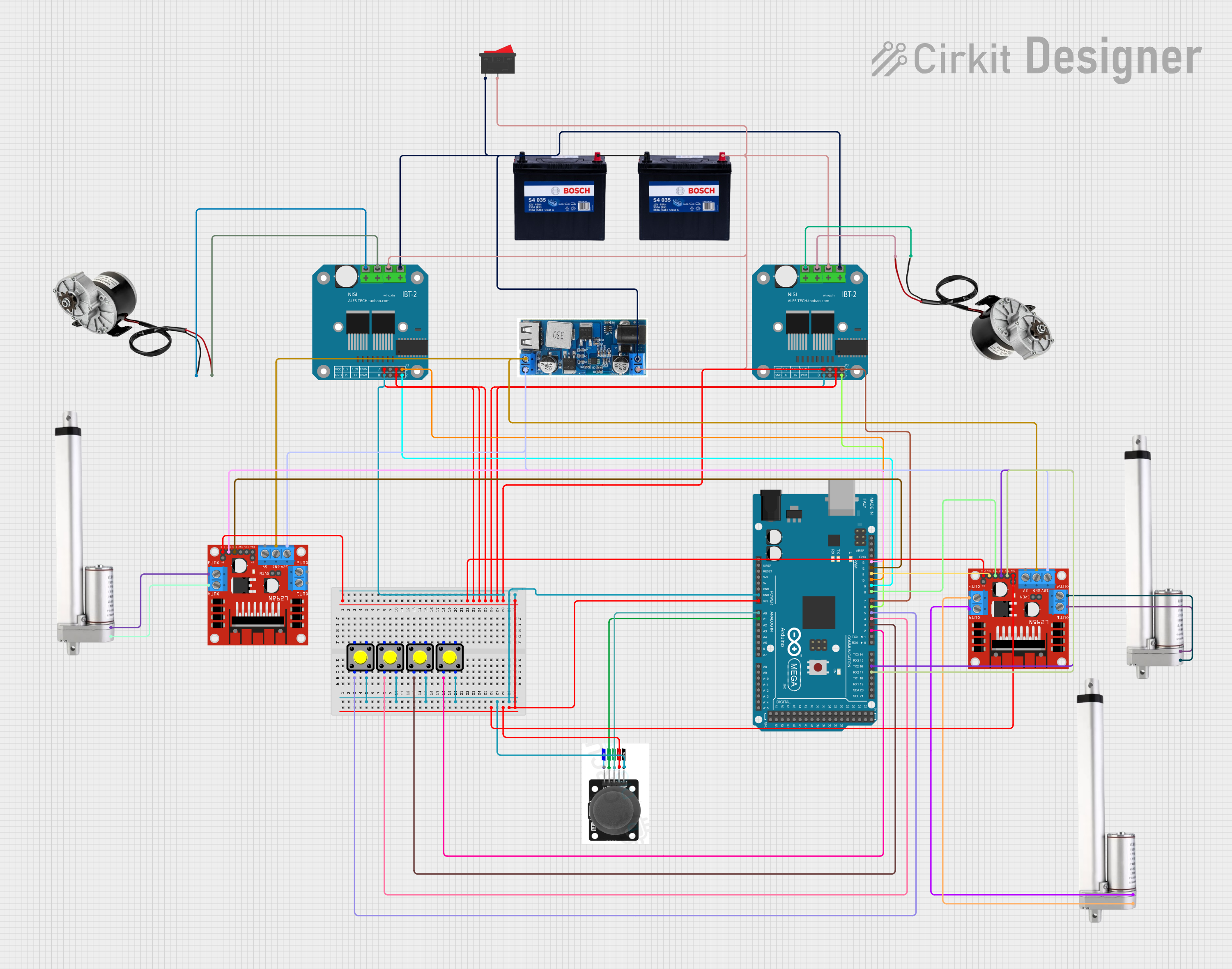
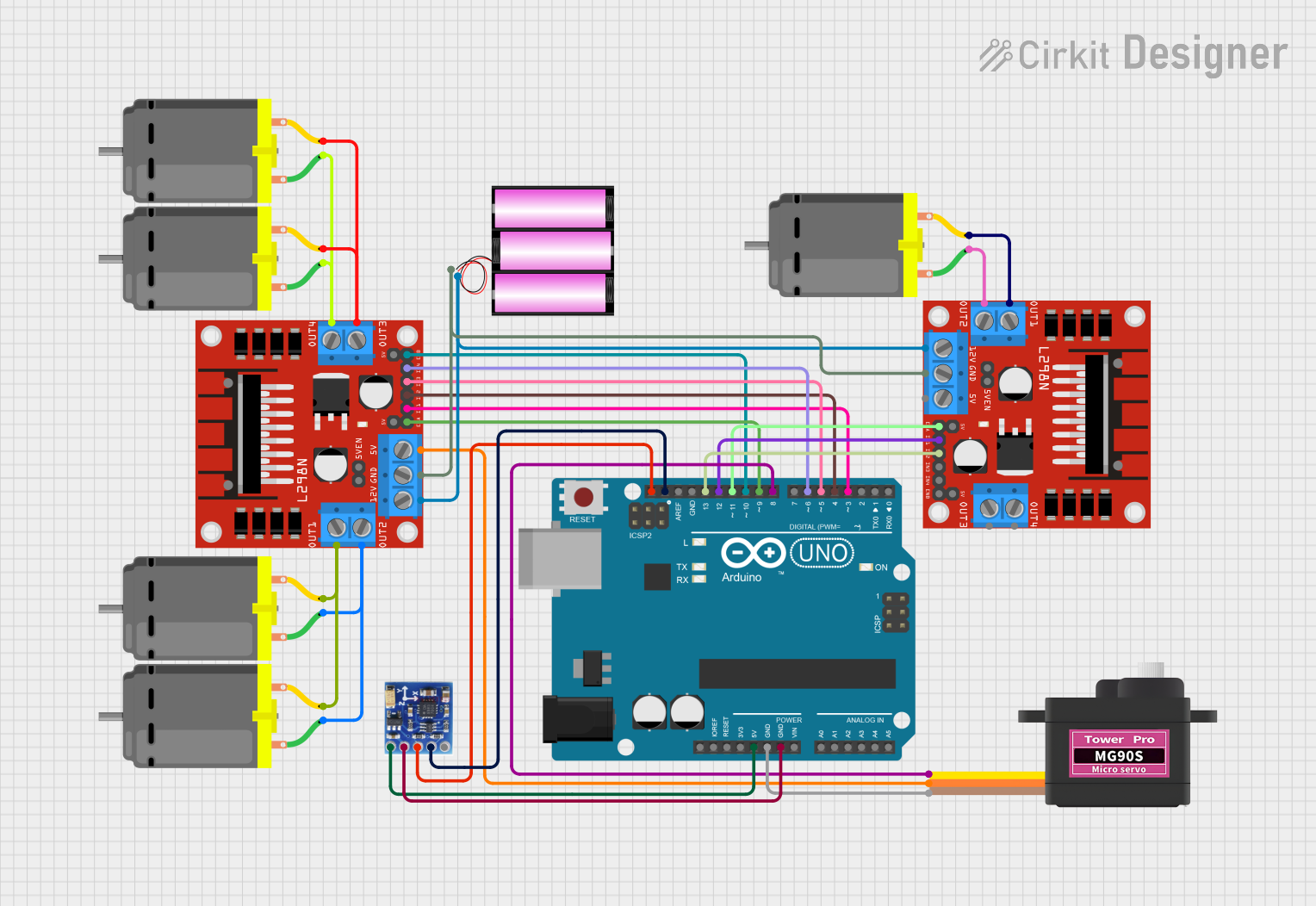
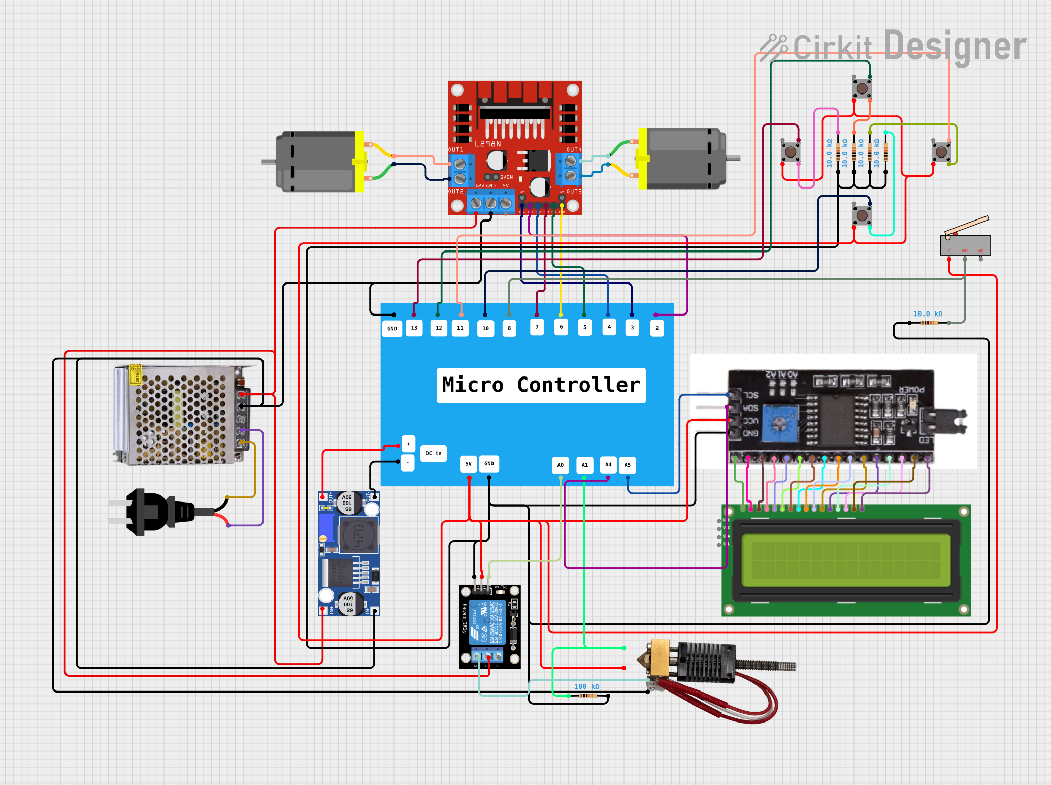
Explore Projects Built with DC-motordriver
Common Applications and Use Cases
- Robotics: Controlling wheels or actuators in robotic systems.
- Conveyor Belts: Adjusting speed and direction in industrial automation.
- Electric Vehicles: Driving small DC motors in scooters or carts.
- Home Automation: Operating motorized curtains, doors, or windows.
- Prototyping: Used in DIY projects and educational setups for motor control.
Technical Specifications
Key Technical Details
| Parameter | Value |
|---|---|
| Manufacturer | Stepper Online |
| Part ID | BLD-405S |
| Input Voltage Range | 12V - 48V DC |
| Maximum Output Current | 5A |
| Control Signal Voltage | 3.3V or 5V logic compatible |
| PWM Frequency Range | 1 kHz - 20 kHz |
| Operating Temperature | -10°C to 45°C |
| Dimensions | 96mm x 56mm x 33mm |
| Weight | 150g |
Pin Configuration and Descriptions
The BLD-405S features a set of input and output terminals for motor control and power connections. Below is the pin configuration:
Power and Motor Connections
| Pin Name | Description |
|---|---|
| V+ | Positive power supply input (12V - 48V DC). |
| GND | Ground connection for the power supply. |
| M+ | Positive terminal of the DC motor. |
| M- | Negative terminal of the DC motor. |
Control Signal Connections
| Pin Name | Description |
|---|---|
| EN | Enable pin: High to enable the motor driver. |
| DIR | Direction control: High for one direction, |
| Low for the opposite direction. | |
| PWM | Pulse Width Modulation input for speed |
| control (1 kHz - 20 kHz). |
Usage Instructions
How to Use the Component in a Circuit
- Power Supply: Connect a DC power supply (12V - 48V) to the
V+andGNDpins. Ensure the power supply can provide sufficient current for the motor. - Motor Connection: Attach the DC motor terminals to the
M+andM-pins. - Control Signals:
- Connect the
ENpin to a logic HIGH (3.3V or 5V) to enable the driver. - Use the
DIRpin to set the motor's rotation direction. - Provide a PWM signal to the
PWMpin to control the motor speed.
- Connect the
Important Considerations and Best Practices
- Voltage Compatibility: Ensure the motor's rated voltage matches the power supply voltage.
- Current Limitation: Do not exceed the maximum output current of 5A to avoid damage.
- Heat Dissipation: Use a heatsink or ensure proper ventilation if the driver operates at high currents for extended periods.
- Signal Integrity: Use shielded cables for control signals in noisy environments to prevent interference.
Example: Connecting to an Arduino UNO
The BLD-405S can be easily interfaced with an Arduino UNO for motor control. Below is an example code snippet:
// Define control pins
const int enablePin = 9;  // Connect to EN pin on BLD-405S
const int dirPin = 8;     // Connect to DIR pin on BLD-405S
const int pwmPin = 10;    // Connect to PWM pin on BLD-405S

void setup() {
  // Set pin modes
  pinMode(enablePin, OUTPUT);
  pinMode(dirPin, OUTPUT);
  pinMode(pwmPin, OUTPUT);

  // Enable the motor driver
  digitalWrite(enablePin, HIGH);
}

void loop() {
  // Set motor direction to forward
  digitalWrite(dirPin, HIGH);

  // Gradually increase motor speed
  for (int speed = 0; speed <= 255; speed++) {
    analogWrite(pwmPin, speed);  // Send PWM signal to control speed
    delay(20);                   // Wait for 20ms
  }

  // Reverse motor direction
  digitalWrite(dirPin, LOW);

  // Gradually decrease motor speed
  for (int speed = 255; speed >= 0; speed--) {
    analogWrite(pwmPin, speed);  // Send PWM signal to control speed
    delay(20);                   // Wait for 20ms
  }
}
Troubleshooting and FAQs
Common Issues and Solutions
Motor Not Spinning:
- Ensure the
ENpin is set to HIGH. - Verify the power supply voltage and current are within the specified range.
- Check motor connections to
M+andM-.
- Ensure the
Motor Spins in the Wrong Direction:
- Reverse the logic level on the
DIRpin. - Alternatively, swap the motor connections on
M+andM-.
- Reverse the logic level on the
Overheating:
- Ensure the driver is not exceeding the 5A current limit.
- Use a heatsink or improve ventilation around the driver.
PWM Signal Not Working:
- Verify the PWM frequency is within the 1 kHz - 20 kHz range.
- Check the Arduino code for correct pin assignments and signal generation.
FAQs
Can I use a 6V motor with the BLD-405S? No, the minimum input voltage is 12V. Using a lower voltage may damage the driver or result in improper operation.
What happens if I exceed the 5A current limit? The driver may overheat or shut down to protect itself. Prolonged overcurrent conditions can permanently damage the driver.
Can I control multiple motors with one BLD-405S? No, the BLD-405S is designed to control a single DC motor. Use separate drivers for additional motors.
This documentation provides a comprehensive guide to using the BLD-405S DC motor driver effectively. For further assistance, refer to the manufacturer's datasheet or contact Stepper Online support.