How to Use Air780EU (Schematic): Examples, Pinouts, and Specs
Introduction
The Air780EU is a compact and efficient cellular module designed specifically for Internet of Things (IoT) applications. It provides LTE connectivity with low power consumption, making it ideal for battery-powered devices. The module supports multiple communication protocols, including TCP/IP, MQTT, and HTTP, enabling seamless integration into remote monitoring and control systems. Its small form factor and robust design make it suitable for a wide range of applications, such as smart meters, asset tracking, industrial automation, and environmental monitoring.
Explore Projects Built with Air780EU (Schematic)
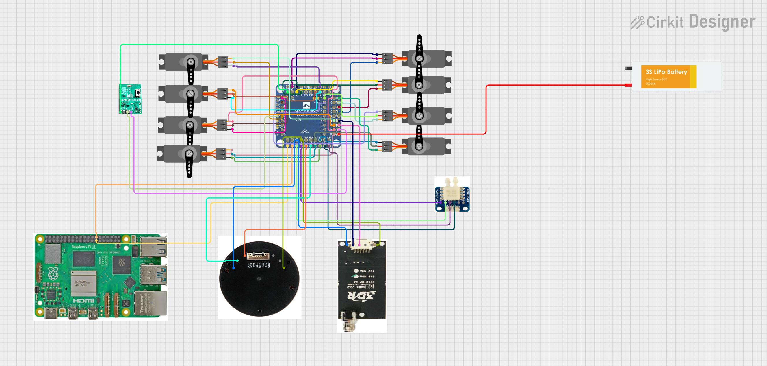


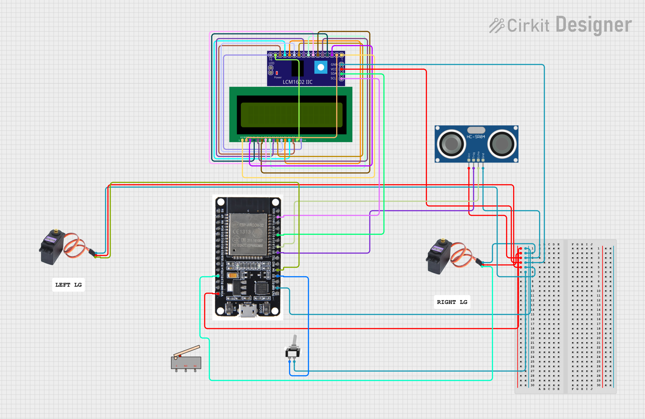
Explore Projects Built with Air780EU (Schematic)
Technical Specifications
Below are the key technical details and pin configuration of the Air780EU module:
Key Technical Details
| Parameter | Specification |
|---|---|
| Cellular Technology | LTE Cat-M1 / NB-IoT |
| Frequency Bands | LTE B1/B3/B5/B8/B20/B28 |
| Communication Protocols | TCP/IP, MQTT, HTTP, CoAP |
| Operating Voltage | 3.3V to 4.2V |
| Power Consumption | < 1mA (sleep mode), ~20mA (active) |
| Operating Temperature | -40°C to +85°C |
| Dimensions | 24mm x 24mm x 2.6mm |
| Interface | UART, GPIO, ADC, I2C |
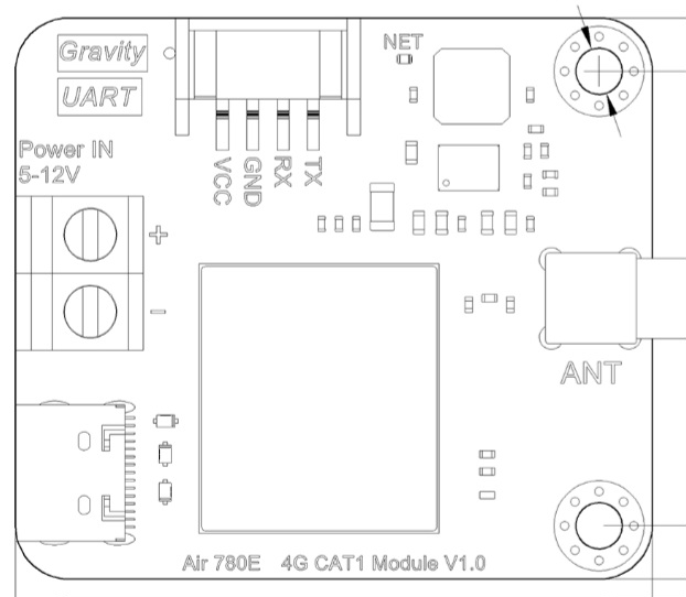
Pin Configuration and Descriptions
The Air780EU module has a total of 24 pins. Below is the pinout description:
| Pin Number | Pin Name | Description |
|---|---|---|
| 1 | VCC | Power supply input (3.3V to 4.2V) |
| 2 | GND | Ground |
| 3 | TXD | UART Transmit |
| 4 | RXD | UART Receive |
| 5 | RTS | UART Ready to Send |
| 6 | CTS | UART Clear to Send |
| 7 | RESET | Module reset (active low) |
| 8 | PWRKEY | Power-on key (active low) |
| 9 | GPIO1 | General-purpose I/O |
| 10 | GPIO2 | General-purpose I/O |
| 11 | ADC | Analog-to-Digital Converter input |
| 12 | I2C_SCL | I2C Clock |
| 13 | I2C_SDA | I2C Data |
| 14 | NET_STATUS | Network status indicator |
| 15 | SIM_DET | SIM card detection |
| 16 | ANT | Antenna connection |
| 17-24 | Reserved | Reserved for future use |
Usage Instructions
How to Use the Air780EU in a Circuit
- Power Supply: Connect the VCC pin to a stable power source (3.3V to 4.2V) and GND to the ground of your circuit.
- UART Communication: Use the TXD and RXD pins to establish serial communication with a microcontroller or host device. Ensure the baud rate matches the module's default setting (typically 115200 bps).
- Antenna Connection: Attach an external antenna to the ANT pin for optimal signal reception.
- Power-On Sequence: Pull the PWRKEY pin low for at least 1 second to power on the module.
- Network Status: Monitor the NET_STATUS pin to check the module's connection status.
- SIM Card: Insert a compatible SIM card and connect the SIM_DET pin to detect its presence.
Important Considerations and Best Practices
- Use decoupling capacitors near the VCC pin to ensure stable power delivery.
- Avoid placing the antenna near high-frequency components to minimize interference.
- Ensure proper grounding to reduce noise and improve signal quality.
- Use level shifters if interfacing with a microcontroller operating at a different voltage level.
Example: Connecting Air780EU to Arduino UNO
Below is an example of how to connect the Air780EU to an Arduino UNO and send an AT command to check the module's status:
Wiring Diagram
| Air780EU Pin | Arduino UNO Pin |
|---|---|
| VCC | 3.3V |
| GND | GND |
| TXD | D2 (RX) |
| RXD | D3 (TX) |
| PWRKEY | D4 |
Arduino Code
#include <SoftwareSerial.h>

// Define software serial pins for Air780EU communication
SoftwareSerial air780Serial(2, 3); // RX, TX

#define PWRKEY_PIN 4 // Pin connected to PWRKEY

void setup() {
  // Initialize serial communication
  Serial.begin(9600); // For debugging
  air780Serial.begin(115200); // For Air780EU communication

  // Configure PWRKEY pin
  pinMode(PWRKEY_PIN, OUTPUT);
  digitalWrite(PWRKEY_PIN, HIGH); // Set PWRKEY high initially

  // Power on the Air780EU module
  Serial.println("Powering on Air780EU...");
  digitalWrite(PWRKEY_PIN, LOW); // Pull PWRKEY low
  delay(1000); // Hold for 1 second
  digitalWrite(PWRKEY_PIN, HIGH); // Release PWRKEY
  delay(5000); // Wait for the module to initialize

  // Send an AT command to check module status
  Serial.println("Sending AT command...");
  air780Serial.println("AT");
}

void loop() {
  // Read and display responses from the Air780EU module
  if (air780Serial.available()) {
    String response = air780Serial.readString();
    Serial.println("Air780EU Response: " + response);
  }
}
Troubleshooting and FAQs
Common Issues and Solutions
Module Not Powering On
- Ensure the PWRKEY pin is pulled low for at least 1 second during the power-on sequence.
- Verify that the power supply voltage is within the specified range (3.3V to 4.2V).
No Response to AT Commands
- Check the UART connections (TXD and RXD) and ensure they are not swapped.
- Confirm that the baud rate of the microcontroller matches the module's default baud rate (115200 bps).
Poor Signal Reception
- Ensure the antenna is securely connected to the ANT pin.
- Avoid placing the module in areas with significant electromagnetic interference.
SIM Card Not Detected
- Verify that the SIM card is properly inserted and compatible with the module.
- Check the SIM_DET pin connection.
FAQs
Q: Can the Air780EU operate on 5V logic levels?
A: No, the Air780EU operates on 3.3V logic levels. Use level shifters if interfacing with a 5V microcontroller.
Q: What is the typical startup time for the module?
A: The Air780EU typically takes 3-5 seconds to initialize after powering on.
Q: Does the module support GPS functionality?
A: No, the Air780EU does not include GPS functionality. It is designed for LTE connectivity only.