Cirkit Designer Logo
Cirkit Designer
Your all-in-one circuit design IDE
Home / 
Component Documentation

How to Use esp32-wr00m-32 dev 1: Examples, Pinouts, and Specs

Image of esp32-wr00m-32 dev 1
Cirkit Designer LogoDesign with esp32-wr00m-32 dev 1 in Cirkit Designer

Introduction

The ESP32-WROOM-32 is a versatile Wi-Fi and Bluetooth microcontroller module designed for Internet of Things (IoT) applications. It features dual-core processing, low power consumption, and a wide range of connectivity options, making it ideal for smart devices, home automation, wearables, and industrial IoT solutions. Its compact design and robust performance allow developers to create innovative and efficient projects with ease.

Explore Projects Built with esp32-wr00m-32 dev 1

Use Cirkit Designer to design, explore, and prototype these projects online. Some projects support real-time simulation. Click "Open Project" to start designing instantly!
ESP32-Based GPS Tracker with SD Card Logging and Barometric Sensor
Image of gps projekt circuit: A project utilizing esp32-wr00m-32 dev 1 in a practical application
This circuit features an ESP32 Wroom Dev Kit as the main microcontroller, interfaced with an MPL3115A2 sensor for pressure and temperature readings, and a Neo 6M GPS module for location tracking. The ESP32 is also connected to an SD card reader for data logging purposes. A voltage regulator is used to step down the USB power supply to 3.3V, which powers the ESP32, the sensor, and the SD card reader.
Cirkit Designer LogoOpen Project in Cirkit Designer
ESP32-Based Multi-Sensor Health Monitoring System with Bluetooth Connectivity
Image of circuit diagram: A project utilizing esp32-wr00m-32 dev 1 in a practical application
This circuit features an ESP32-WROOM-32UE microcontroller as the central processing unit, interfacing with a variety of sensors and modules. It includes a MAX30100 pulse oximeter and heart-rate sensor, an MLX90614 infrared thermometer, an HC-05 Bluetooth module for wireless communication, and a Neo 6M GPS module for location tracking. All components are powered by a common voltage supply and are connected to specific GPIO pins on the ESP32 for data exchange, with the sensors using I2C communication and the modules using UART.
Cirkit Designer LogoOpen Project in Cirkit Designer
ESP32-Based Environmental Monitoring System with Water Flow Sensing
Image of Water: A project utilizing esp32-wr00m-32 dev 1 in a practical application
This circuit features an ESP32 Devkit V1 microcontroller connected to a DHT22 temperature and humidity sensor and a water flow sensor. The ESP32 reads environmental data from the DHT22 via a digital input pin (D33) and monitors water flow through the water flow sensor connected to another digital input pin (D23). The ESP32 is powered through its VIN pin, and both sensors are powered by the ESP32's 3V3 output, with common ground connections.
Cirkit Designer LogoOpen Project in Cirkit Designer
ESP32 and Arduino UNO Serial Communication Interface
Image of ESP32 Arduino COM SErial: A project utilizing esp32-wr00m-32 dev 1 in a practical application
This circuit integrates an ESP32 Wroom Dev Kit and an Arduino UNO, connected via their TXD/RXD pins for serial communication and sharing a common ground. Both microcontrollers are programmed with basic setup and loop functions, indicating a potential for further development of communication or control tasks.
Cirkit Designer LogoOpen Project in Cirkit Designer

Explore Projects Built with esp32-wr00m-32 dev 1

Use Cirkit Designer to design, explore, and prototype these projects online. Some projects support real-time simulation. Click "Open Project" to start designing instantly!
Image of gps projekt circuit: A project utilizing esp32-wr00m-32 dev 1 in a practical application
ESP32-Based GPS Tracker with SD Card Logging and Barometric Sensor
This circuit features an ESP32 Wroom Dev Kit as the main microcontroller, interfaced with an MPL3115A2 sensor for pressure and temperature readings, and a Neo 6M GPS module for location tracking. The ESP32 is also connected to an SD card reader for data logging purposes. A voltage regulator is used to step down the USB power supply to 3.3V, which powers the ESP32, the sensor, and the SD card reader.
Cirkit Designer LogoOpen Project in Cirkit Designer
Image of circuit diagram: A project utilizing esp32-wr00m-32 dev 1 in a practical application
ESP32-Based Multi-Sensor Health Monitoring System with Bluetooth Connectivity
This circuit features an ESP32-WROOM-32UE microcontroller as the central processing unit, interfacing with a variety of sensors and modules. It includes a MAX30100 pulse oximeter and heart-rate sensor, an MLX90614 infrared thermometer, an HC-05 Bluetooth module for wireless communication, and a Neo 6M GPS module for location tracking. All components are powered by a common voltage supply and are connected to specific GPIO pins on the ESP32 for data exchange, with the sensors using I2C communication and the modules using UART.
Cirkit Designer LogoOpen Project in Cirkit Designer
Image of Water: A project utilizing esp32-wr00m-32 dev 1 in a practical application
ESP32-Based Environmental Monitoring System with Water Flow Sensing
This circuit features an ESP32 Devkit V1 microcontroller connected to a DHT22 temperature and humidity sensor and a water flow sensor. The ESP32 reads environmental data from the DHT22 via a digital input pin (D33) and monitors water flow through the water flow sensor connected to another digital input pin (D23). The ESP32 is powered through its VIN pin, and both sensors are powered by the ESP32's 3V3 output, with common ground connections.
Cirkit Designer LogoOpen Project in Cirkit Designer
Image of ESP32 Arduino COM SErial: A project utilizing esp32-wr00m-32 dev 1 in a practical application
ESP32 and Arduino UNO Serial Communication Interface
This circuit integrates an ESP32 Wroom Dev Kit and an Arduino UNO, connected via their TXD/RXD pins for serial communication and sharing a common ground. Both microcontrollers are programmed with basic setup and loop functions, indicating a potential for further development of communication or control tasks.
Cirkit Designer LogoOpen Project in Cirkit Designer

Common Applications and Use Cases

  • Smart home devices (e.g., smart lights, thermostats)
  • Wearable technology
  • Industrial IoT systems
  • Wireless sensor networks
  • Robotics and automation
  • Real-time data monitoring and logging

Technical Specifications

The ESP32-WROOM-32 module is built around the ESP32-D0WDQ6 chip, offering a rich set of features for various applications.

Key Technical Details

Parameter Specification
Microcontroller ESP32-D0WDQ6 (dual-core Xtensa LX6)
Clock Speed Up to 240 MHz
Flash Memory 4 MB (default)
SRAM 520 KB
Wi-Fi Standards 802.11 b/g/n (2.4 GHz)
Bluetooth v4.2 BR/EDR and BLE
Operating Voltage 3.0V to 3.6V
GPIO Pins 34
ADC Channels 18 (12-bit resolution)
DAC Channels 2
Communication Interfaces UART, SPI, I2C, I2S, CAN, PWM
Power Consumption Ultra-low power (deep sleep: ~10 µA)
Operating Temperature -40°C to +85°C

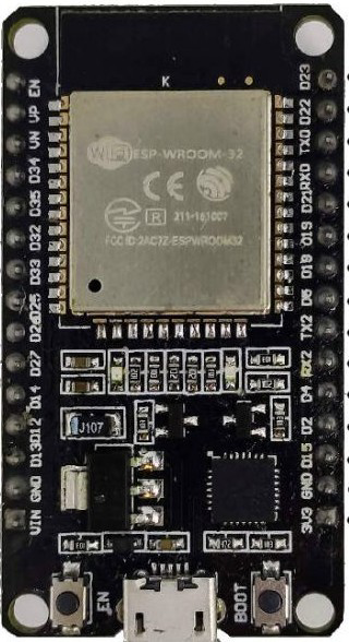
Pin Configuration and Descriptions

The ESP32-WROOM-32 module has 38 pins. Below is a table of the most commonly used pins and their functions:

Pin Number Pin Name Function Description
1 EN Enable pin (active high)
2 GPIO0 Boot mode selection / General-purpose IO
3 GPIO1 (TX) UART0 Transmit
4 GPIO3 (RX) UART0 Receive
5 GPIO2 General-purpose IO
6 GPIO4 General-purpose IO
7 GPIO5 General-purpose IO
8 GPIO12 General-purpose IO / ADC2 Channel 5
9 GPIO13 General-purpose IO / ADC2 Channel 4
10 GPIO14 General-purpose IO / ADC2 Channel 6
11 GPIO15 General-purpose IO / ADC2 Channel 3
12 GPIO16 General-purpose IO
13 GPIO17 General-purpose IO
14 3V3 3.3V Power Output
15 GND Ground

For a complete pinout, refer to the ESP32-WROOM-32 datasheet.
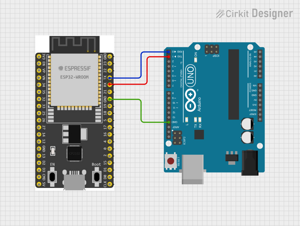
Usage Instructions

How to Use the ESP32-WROOM-32 in a Circuit

  1. Power Supply: Provide a stable 3.3V power supply to the module. Avoid exceeding 3.6V to prevent damage.
  2. Boot Mode: Connect GPIO0 to GND during power-up to enter bootloader mode for programming.
  3. Communication: Use UART, SPI, or I2C interfaces to communicate with other devices.
  4. GPIO Usage: Configure GPIO pins as input or output in your code. Be mindful of pins with special functions (e.g., ADC, DAC).
  5. Programming: Use the Arduino IDE or ESP-IDF (Espressif IoT Development Framework) to write and upload code.

Important Considerations and Best Practices

  • Voltage Levels: Ensure all connected devices operate at 3.3V logic levels. Use level shifters if necessary.
  • Deep Sleep Mode: Utilize deep sleep mode to minimize power consumption in battery-powered applications.
  • Antenna Placement: Avoid placing metal objects near the onboard antenna to maintain strong Wi-Fi and Bluetooth signals.
  • Pin Limitations: Some GPIO pins have restrictions (e.g., GPIO6-GPIO11 are used for flash memory and should not be used for general I/O).

Example Code for Arduino UNO

Below is an example of how to blink an LED connected to GPIO2 using the Arduino IDE:

// Define the GPIO pin for the LED
#define LED_PIN 2

void setup() {
  // Set the LED pin as an output
  pinMode(LED_PIN, OUTPUT);
}

void loop() {
  // Turn the LED on
  digitalWrite(LED_PIN, HIGH);
  delay(1000); // Wait for 1 second

  // Turn the LED off
  digitalWrite(LED_PIN, LOW);
  delay(1000); // Wait for 1 second
}

Troubleshooting and FAQs

Common Issues and Solutions

  1. Module Not Responding

    • Cause: Incorrect power supply or wiring.
    • Solution: Verify that the module is receiving a stable 3.3V supply and check all connections.
  2. Wi-Fi Connection Fails

    • Cause: Weak signal or incorrect credentials.
    • Solution: Ensure the module is within range of the Wi-Fi router and double-check the SSID and password.
  3. Code Upload Fails

    • Cause: Incorrect boot mode or COM port selection.
    • Solution: Hold GPIO0 low during power-up to enter bootloader mode and select the correct COM port in the IDE.
  4. GPIO Pin Not Working

    • Cause: Pin conflict or incorrect configuration.
    • Solution: Check if the pin is reserved for special functions and ensure it is properly configured in the code.

FAQs

  • Q: Can the ESP32-WROOM-32 operate on 5V?
    A: No, the module operates on 3.3V. Use a voltage regulator or level shifter for 5V systems.

  • Q: How do I reset the module?
    A: Press the EN (enable) pin or connect it to GND momentarily to reset the module.

  • Q: Can I use the ESP32-WROOM-32 for both Wi-Fi and Bluetooth simultaneously?
    A: Yes, the ESP32 supports simultaneous Wi-Fi and Bluetooth operation.

  • Q: What is the maximum range of the Wi-Fi connection?
    A: The range depends on environmental factors but typically extends up to 100 meters in open space.

This documentation provides a comprehensive guide to using the ESP32-WROOM-32 module effectively. For further details, refer to the official datasheet and Espressif's documentation.