Cirkit Designer Logo
Cirkit Designer
Your all-in-one circuit design IDE
Home / 
Component Documentation

How to Use Industrial Pressure Sensor: Examples, Pinouts, and Specs

Image of Industrial Pressure Sensor
Cirkit Designer LogoDesign with Industrial Pressure Sensor in Cirkit Designer

Introduction

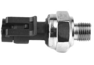
An Industrial Pressure Sensor is a critical component used to measure the pressure of gases or liquids in industrial settings. These sensors are engineered to endure the rigors of harsh environments, including extreme temperatures, vibrations, and corrosive materials. They are commonly used in applications such as hydraulic systems, pneumatic systems, process control, and automation.

Explore Projects Built with Industrial Pressure Sensor

Use Cirkit Designer to design, explore, and prototype these projects online. Some projects support real-time simulation. Click "Open Project" to start designing instantly!
ESP32-Controlled Pressure Monitoring System with ADS1115 and Darlington Transistor Switching
Image of Pressuer Sensor Test Rig: A project utilizing Industrial Pressure Sensor in a practical application
This circuit is designed to measure pressure using a transducer, convert the analog signal to digital with an ADS1115 ADC, and process and display the data on an ESP32 microcontroller with a 7-inch screen. It includes power regulation and filtering, as well as a Darlington transistor for load control.
Cirkit Designer LogoOpen Project in Cirkit Designer
Wi-Fi Enabled Water Monitoring System with ESP8266
Image of Copy of automatic water leak detection: A project utilizing Industrial Pressure Sensor in a practical application
This circuit monitors water pressure and flow using a Gravity analog water pressure sensor and a water flow sensor, respectively. The sensors are powered by a 5V adapter and their signals are read by an ESP8266 microcontroller, which can process and transmit the data for further use.
Cirkit Designer LogoOpen Project in Cirkit Designer
Wi-Fi Enabled Water Monitoring System with ESP8266
Image of automatic water leak detection: A project utilizing Industrial Pressure Sensor in a practical application
This circuit monitors water pressure and flow using a Gravity analog water pressure sensor and a water flow sensor, respectively. The sensors are powered by a 5V adapter and their signals are read by an ESP8266 microcontroller, which can process and transmit the data for further use.
Cirkit Designer LogoOpen Project in Cirkit Designer
ESP32 and ESP8266 Wi-Fi Controlled Sensor Hub with Battery Backup
Image of baby guard: A project utilizing Industrial Pressure Sensor in a practical application
This circuit is a sensor monitoring and data transmission system powered by a Li-ion battery and a 12V adapter. It includes various sensors (tilt, optical encoder, force sensing resistors, and air pressure) connected to an ESP32 microcontroller, which reads sensor data and transmits it via a WiFi module (ESP8266-01). The system is designed to provide real-time sensor data over a WiFi network.
Cirkit Designer LogoOpen Project in Cirkit Designer

Explore Projects Built with Industrial Pressure Sensor

Use Cirkit Designer to design, explore, and prototype these projects online. Some projects support real-time simulation. Click "Open Project" to start designing instantly!
Image of Pressuer Sensor Test Rig: A project utilizing Industrial Pressure Sensor in a practical application
ESP32-Controlled Pressure Monitoring System with ADS1115 and Darlington Transistor Switching
This circuit is designed to measure pressure using a transducer, convert the analog signal to digital with an ADS1115 ADC, and process and display the data on an ESP32 microcontroller with a 7-inch screen. It includes power regulation and filtering, as well as a Darlington transistor for load control.
Cirkit Designer LogoOpen Project in Cirkit Designer
Image of Copy of automatic water leak detection: A project utilizing Industrial Pressure Sensor in a practical application
Wi-Fi Enabled Water Monitoring System with ESP8266
This circuit monitors water pressure and flow using a Gravity analog water pressure sensor and a water flow sensor, respectively. The sensors are powered by a 5V adapter and their signals are read by an ESP8266 microcontroller, which can process and transmit the data for further use.
Cirkit Designer LogoOpen Project in Cirkit Designer
Image of automatic water leak detection: A project utilizing Industrial Pressure Sensor in a practical application
Wi-Fi Enabled Water Monitoring System with ESP8266
This circuit monitors water pressure and flow using a Gravity analog water pressure sensor and a water flow sensor, respectively. The sensors are powered by a 5V adapter and their signals are read by an ESP8266 microcontroller, which can process and transmit the data for further use.
Cirkit Designer LogoOpen Project in Cirkit Designer
Image of baby guard: A project utilizing Industrial Pressure Sensor in a practical application
ESP32 and ESP8266 Wi-Fi Controlled Sensor Hub with Battery Backup
This circuit is a sensor monitoring and data transmission system powered by a Li-ion battery and a 12V adapter. It includes various sensors (tilt, optical encoder, force sensing resistors, and air pressure) connected to an ESP32 microcontroller, which reads sensor data and transmits it via a WiFi module (ESP8266-01). The system is designed to provide real-time sensor data over a WiFi network.
Cirkit Designer LogoOpen Project in Cirkit Designer

Technical Specifications

General Specifications

  • Pressure Range: 0 to 1.6 MPa
  • Output Signal: 4-20 mA (current loop)
  • Supply Voltage: 12 to 36 VDC
  • Accuracy: ±0.5% FS (Full Scale)
  • Operating Temperature: -40°C to 85°C
  • Process Connection: 1/4" NPT Male
  • Electrical Connection: DIN 43650 Connector
  • Protection Rating: IP67

Pin Configuration and Descriptions

Pin Number Description Notes
1 +V (Power Supply) Connect to 12-36 VDC
2 Output (4-20 mA) Connect to current loop input
3 Common (Ground) Connect to system ground

Usage Instructions

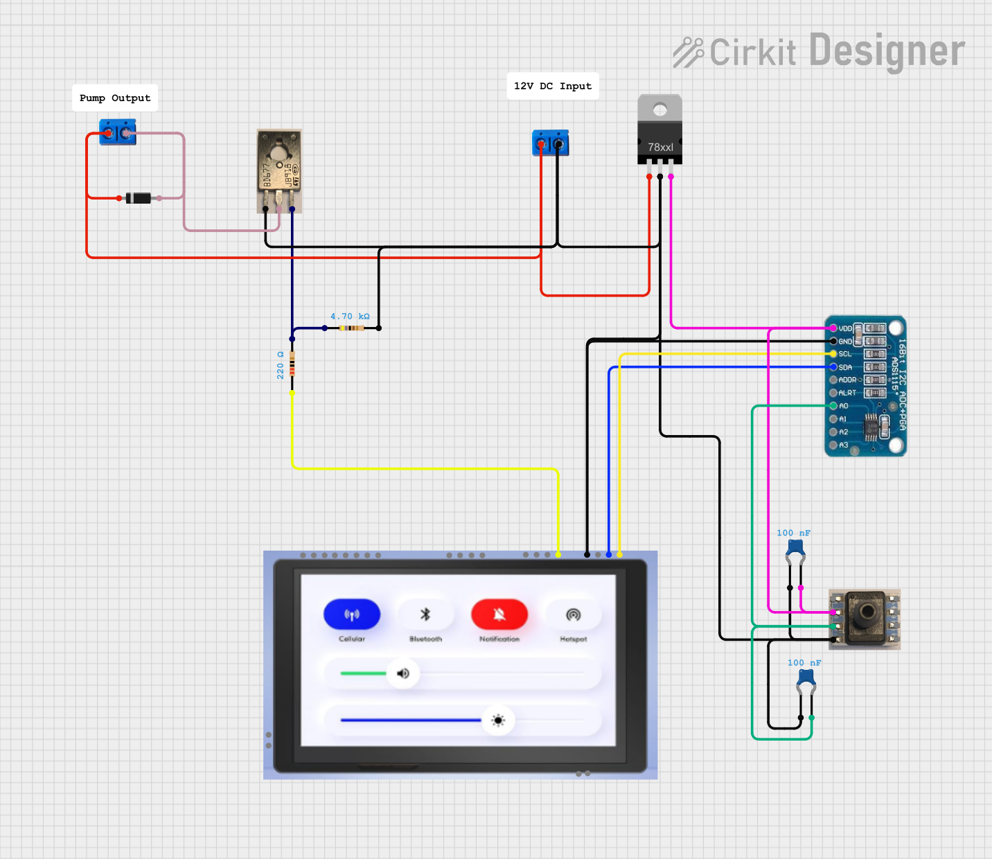
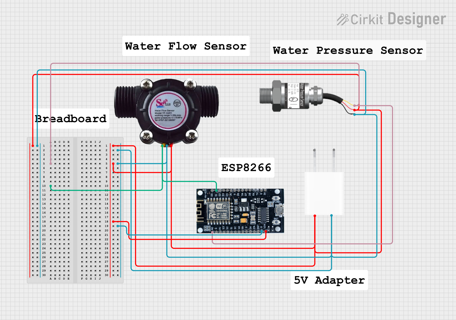
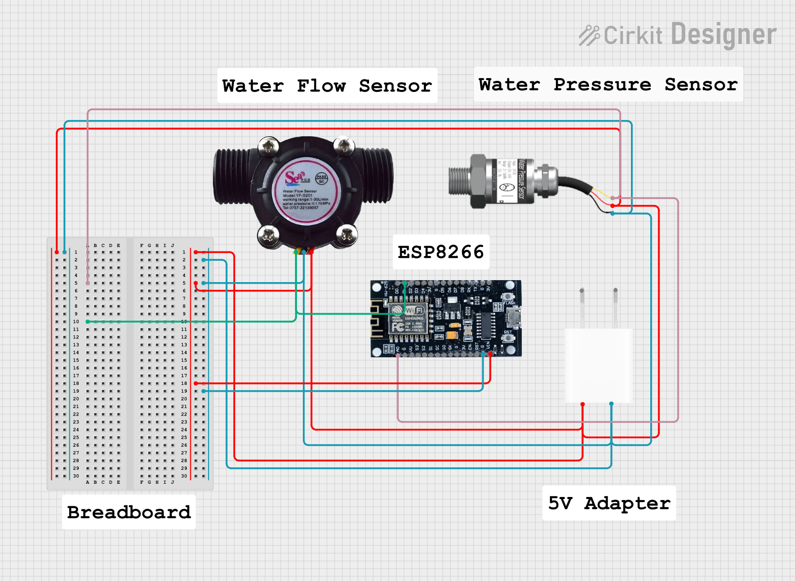
Integration into a Circuit

  1. Power Supply Connection: Connect the sensor's power supply pin to a stable DC voltage source between 12 and 36 volts.
  2. Output Connection: Connect the sensor's output pin to the current loop input of your monitoring or control device.
  3. Grounding: Connect the sensor's ground pin to the common ground in your system to complete the circuit.

Best Practices

  • Calibration: Before use, calibrate the sensor according to the manufacturer's instructions to ensure accurate readings.
  • Installation: Ensure the sensor is installed with the correct orientation and securely tightened to the process connection.
  • Cabling: Use shielded cables for the connections to minimize electrical noise and interference.
  • Environmental Protection: Although the sensor is rated IP67, avoid submerging the sensor unless it is specified for submersion.

Troubleshooting and FAQs

Common Issues and Solutions

  • Inaccurate Readings: Check for proper calibration. Ensure that the sensor is not exposed to pressures beyond its specified range.
  • No Output Signal: Verify the power supply voltage and connections. Check for any damage to the sensor or wiring.
  • Fluctuating Readings: Ensure there is no air in the system for liquid pressure measurements. Check for electrical interference and proper grounding.

FAQs

Q: Can the sensor be used with any type of liquid or gas? A: The sensor is designed for use with a variety of media, but always check the compatibility with specific chemicals and conditions.

Q: What is the significance of the 4-20 mA output signal? A: The 4-20 mA current loop is a standard for transmitting sensor data over long distances with high immunity to electrical noise.

Q: How often should the sensor be calibrated? A: Calibration frequency depends on the usage and environmental conditions. Refer to the manufacturer's recommendations for guidance.

Example Arduino UNO Code

// This example demonstrates how to read a 4-20 mA pressure sensor using an Arduino UNO.

const int sensorPin = A0; // Analog input pin connected to the sensor output

void setup() {
  Serial.begin(9600); // Start serial communication at 9600 baud
}

void loop() {
  int sensorValue = analogRead(sensorPin); // Read the sensor output
  float current = map(sensorValue, 0, 1023, 4, 20); // Map the analog value to 4-20 mA
  float pressure = (current - 4) * (1.6 / 16); // Convert current to pressure in MPa

  Serial.print("Pressure: ");
  Serial.print(pressure);
  Serial.println(" MPa");

  delay(1000); // Wait for a second before reading again
}

Note: The map function in the code is a simple linear approximation. For more accurate results, use a calibrated conversion method.

This documentation provides a comprehensive guide to using a generic Industrial Pressure Sensor with a 1.6 MPa range. For further assistance, consult the manufacturer's datasheet and technical support resources.