How to Use Arducam: Examples, Pinouts, and Specs
Introduction
Arducam is a versatile brand of camera modules designed for integration with microcontrollers and single-board computers, such as Raspberry Pi and Arduino. These modules support a variety of resolutions and features, making them ideal for capturing images and video in numerous applications. Common use cases include robotics, surveillance systems, IoT projects, and machine vision tasks. Arducam modules are known for their ease of use, compatibility, and ability to meet the needs of both hobbyists and professionals.
Explore Projects Built with Arducam
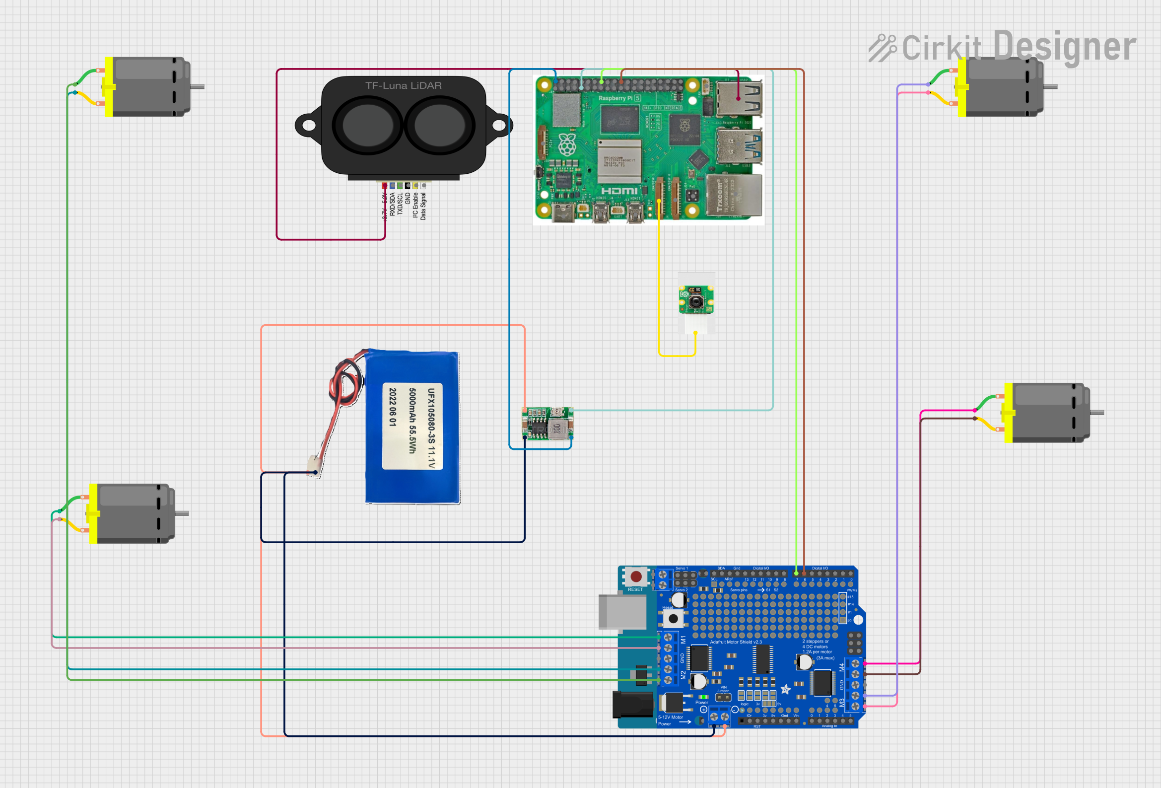
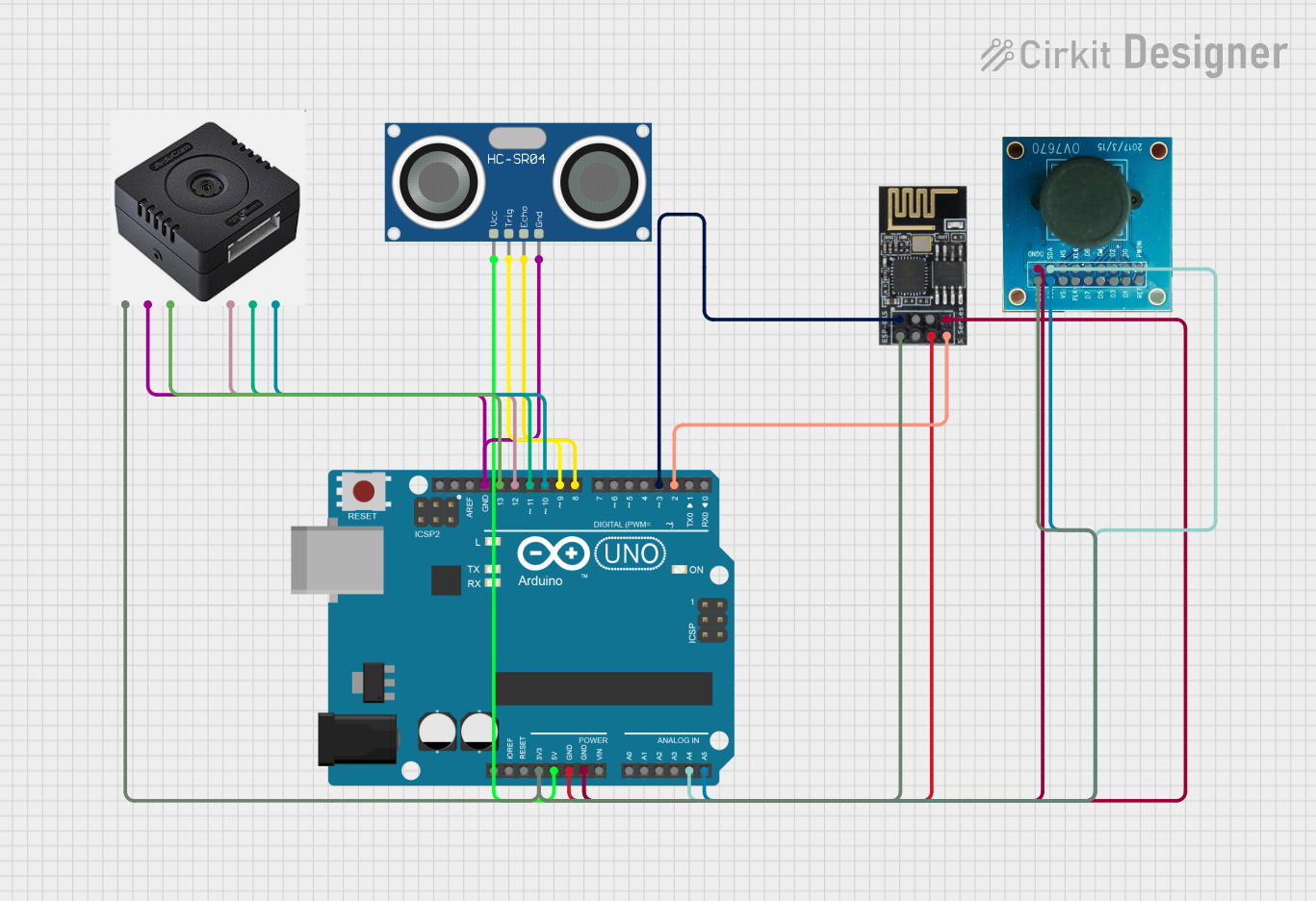
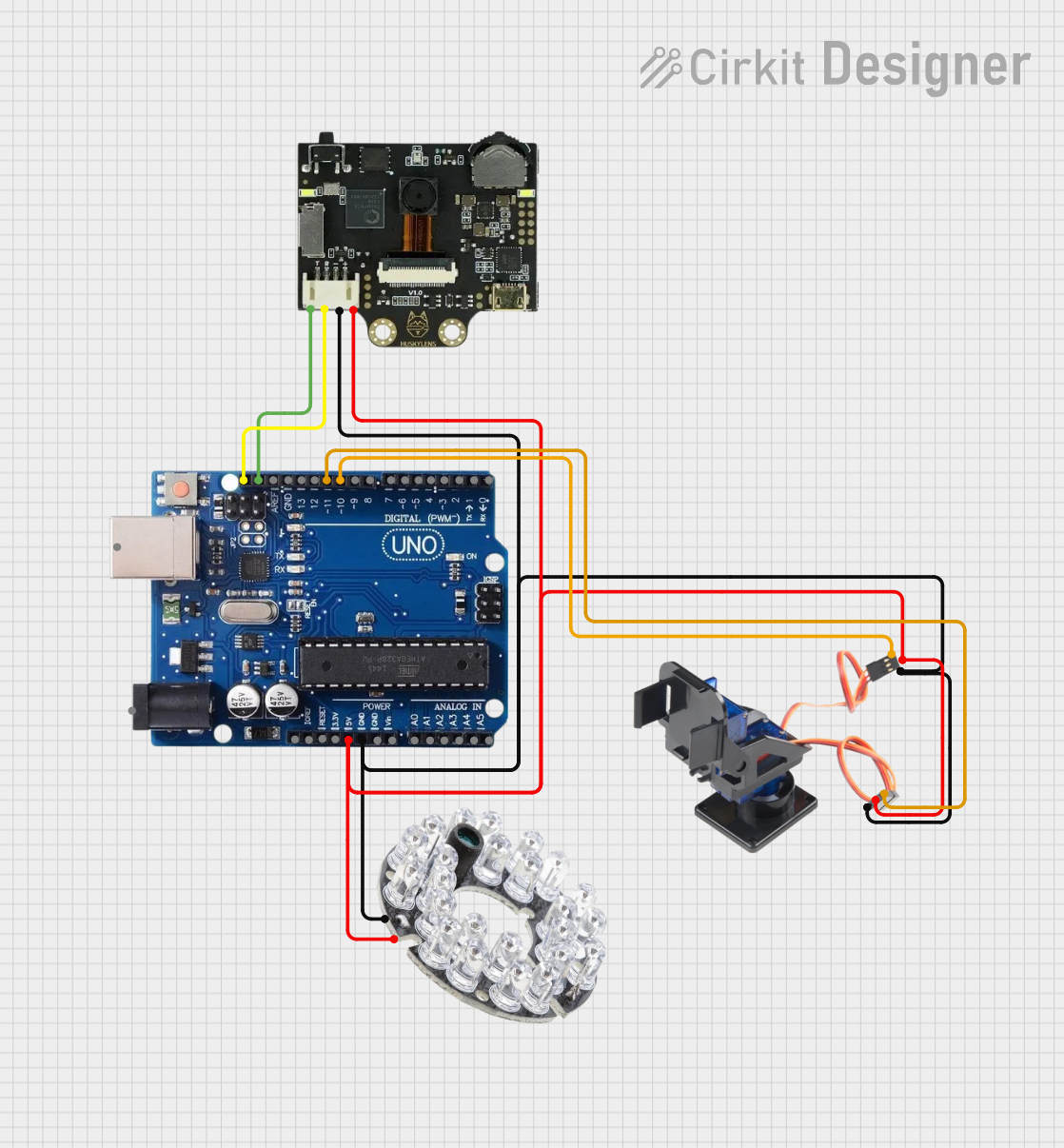

Explore Projects Built with Arducam
Technical Specifications
Arducam modules come in various models, each with unique specifications. Below are the general technical details for a typical Arducam module:
- Resolution: Up to 1080p (depending on the model)
- Interface: SPI, I2C, or CSI (Camera Serial Interface)
- Power Supply: 3.3V or 5V (model-dependent)
- Lens Type: Fixed focus or motorized focus
- Image Sensor: CMOS
- Frame Rate: Up to 30 FPS (model-dependent)
- Compatibility: Arduino, Raspberry Pi, NVIDIA Jetson, and other platforms
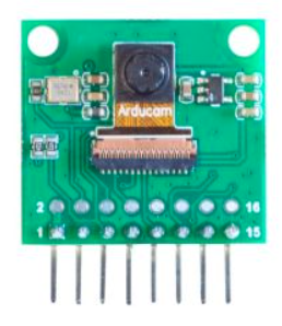
Pin Configuration and Descriptions
The pin configuration may vary depending on the specific Arducam model. Below is an example pinout for an Arducam SPI camera module:
| Pin Name | Description |
|---|---|
| VCC | Power supply (3.3V or 5V) |
| GND | Ground |
| SCL | Serial Clock Line (I2C interface) |
| SDA | Serial Data Line (I2C interface) |
| CS | Chip Select (SPI interface) |
| MOSI | Master Out Slave In (SPI interface) |
| MISO | Master In Slave Out (SPI interface) |
| SCK | Serial Clock (SPI interface) |
| RESET | Reset pin for the camera module |
Refer to the datasheet of your specific Arducam model for exact pin configurations.
Usage Instructions
How to Use the Arducam in a Circuit
- Power the Module: Connect the VCC and GND pins to the appropriate power supply (3.3V or 5V, depending on the model).
- Connect Communication Lines:
- For SPI communication, connect the CS, MOSI, MISO, and SCK pins to the corresponding pins on your microcontroller.
- For I2C communication, connect the SCL and SDA pins to the I2C bus of your microcontroller.
- Install Required Libraries: Download and install the Arducam library for your platform (e.g., Arduino IDE or Raspberry Pi).
- Write Code: Use the library functions to initialize the camera, capture images, and process data.
Important Considerations and Best Practices
- Ensure the power supply voltage matches the module's requirements to avoid damage.
- Use appropriate pull-up resistors for I2C communication if not already included on the module.
- Avoid exposing the camera lens to direct sunlight for extended periods to prevent sensor damage.
- Handle the module carefully to avoid static discharge, which can damage sensitive components.
Example Code for Arduino UNO
Below is an example of how to use an Arducam SPI camera module with an Arduino UNO:
#include <ArduCAM.h>
#include <Wire.h>
#include <SPI.h>

// Define the camera model
#define CAM_CS 10  // Chip Select pin for SPI communication

ArduCAM myCAM(OV2640, CAM_CS);  // Initialize the camera object

void setup() {
  Serial.begin(115200);
  Wire.begin();
  SPI.begin();

  // Initialize the camera
  pinMode(CAM_CS, OUTPUT);
  digitalWrite(CAM_CS, HIGH);
  myCAM.initCAM();

  // Test camera connection
  if (myCAM.checkCameraModule() == false) {
    Serial.println("Camera not detected. Check connections.");
    while (1);
  }
  Serial.println("Camera initialized successfully.");
}

void loop() {
  // Capture an image
  myCAM.startCapture();
  while (!myCAM.checkCaptureComplete()) {
    delay(10);  // Wait for capture to complete
  }
  Serial.println("Image captured!");

  // Read image data (example: save to SD card or send via serial)
  uint8_t buffer[256];
  uint32_t length = myCAM.readImageLength();
  Serial.print("Image size: ");
  Serial.println(length);

  while (length > 0) {
    uint8_t bytesToRead = (length > 256) ? 256 : length;
    myCAM.readImageData(buffer, bytesToRead);
    length -= bytesToRead;

    // Process the buffer (e.g., save to SD card or send via serial)
    Serial.write(buffer, bytesToRead);
  }
  Serial.println("Image transfer complete.");
  delay(5000);  // Wait before capturing the next image
}
Troubleshooting and FAQs
Common Issues
Camera Not Detected:
- Cause: Incorrect wiring or insufficient power supply.
- Solution: Double-check all connections and ensure the power supply matches the module's requirements.
Image Capture Fails:
- Cause: Incorrect initialization or communication issues.
- Solution: Verify that the correct camera model is defined in the code and that the communication pins are properly connected.
Poor Image Quality:
- Cause: Dirty lens or incorrect focus.
- Solution: Clean the lens with a microfiber cloth and adjust the focus if applicable.
Arduino Memory Issues:
- Cause: Insufficient memory for image data.
- Solution: Use an external storage device (e.g., SD card) or a microcontroller with more memory.
FAQs
Can I use Arducam with Raspberry Pi? Yes, Arducam modules are compatible with Raspberry Pi. Use the appropriate libraries and follow the setup instructions for your specific module.
What is the maximum resolution supported? The maximum resolution depends on the specific Arducam model. Refer to the datasheet for details.
Do I need additional drivers? For most platforms, you need to install the Arducam library or driver. Check the official Arducam website for downloads.
Can I use multiple Arducam modules simultaneously? Yes, but you need to configure each module with a unique address or chip select pin, depending on the communication protocol.
By following this documentation, you can effectively integrate and use Arducam modules in your projects.