How to Use LCD Display (16 pin): Examples, Pinouts, and Specs
Introduction
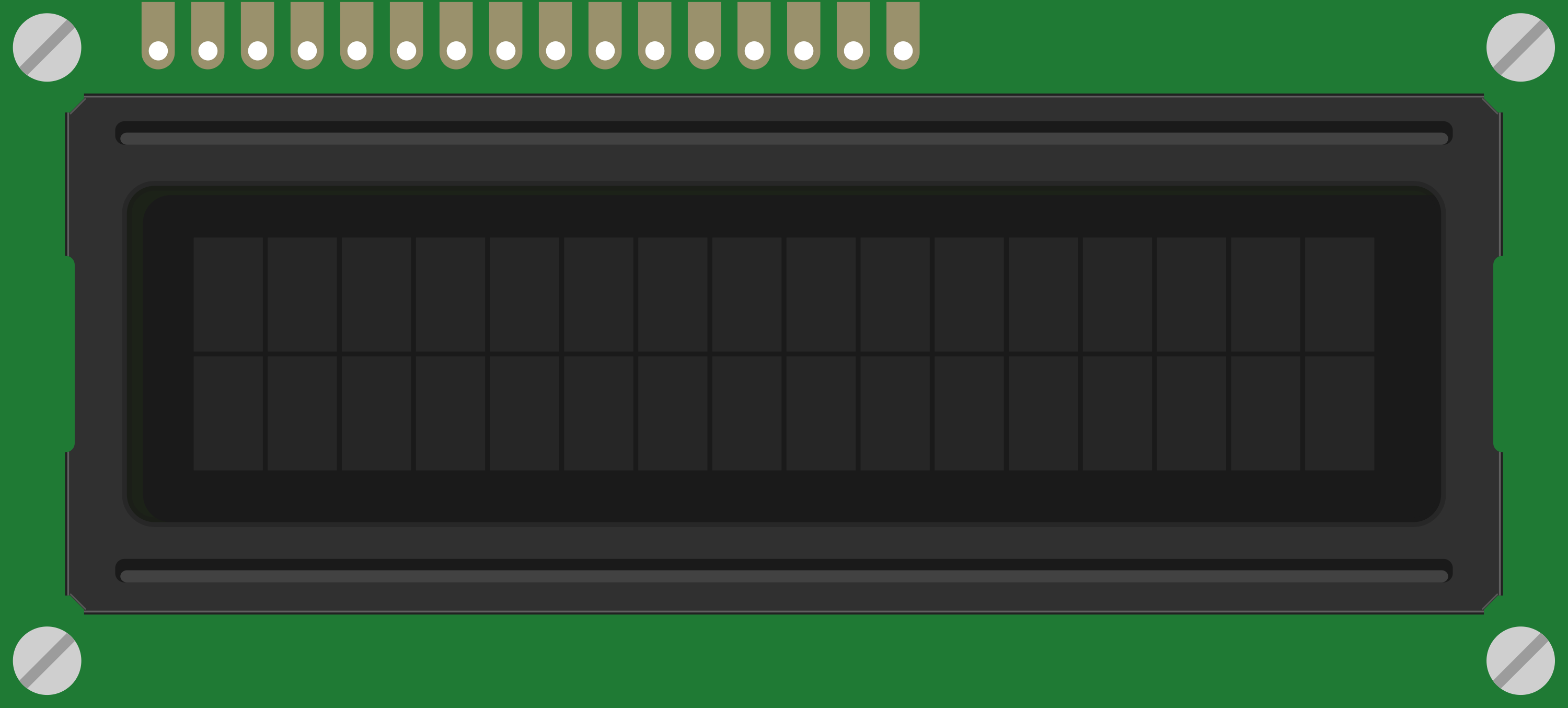
The 16-pin LCD display is a flat-panel display that uses liquid crystals to produce images. It is commonly available in a 2x16 character format, meaning it can display two rows of 16 characters each. This component is widely used for displaying text and simple graphics in embedded systems and microcontroller-based projects. Its 16 pins are allocated for power, ground, data, and control signals, making it versatile and easy to interface with devices like Arduino, Raspberry Pi, and other microcontrollers.
Explore Projects Built with LCD Display (16 pin)

Explore Projects Built with LCD Display (16 pin)
Common Applications and Use Cases
- Digital clocks and timers
- Temperature and humidity monitors
- Home automation systems
- Industrial control panels
- Educational and hobbyist projects
Technical Specifications
Below are the key technical details of the 16-pin LCD display:
| Parameter | Value |
|---|---|
| Display Type | Character LCD |
| Character Format | 2 rows x 16 characters |
| Operating Voltage | 4.7V to 5.3V |
| Operating Current | 1mA to 2mA (without backlight) |
| Backlight Voltage | 4.2V to 4.6V |
| Backlight Current | 120mA (typical) |
| Communication Interface | Parallel (4-bit or 8-bit mode) |
| Operating Temperature | -20°C to +70°C |
Pin Configuration and Descriptions
The 16-pin LCD display has the following pinout:
| Pin Number | Pin Name | Description |
|---|---|---|
| 1 | VSS | Ground (0V) connection |
| 2 | VDD | Power supply (4.7V to 5.3V) |
| 3 | V0 | Contrast adjustment (connect to a potentiometer) |
| 4 | RS | Register Select: 0 = Command, 1 = Data |
| 5 | RW | Read/Write: 0 = Write, 1 = Read |
| 6 | E | Enable pin: Triggers data read/write |
| 7 | D0 | Data bit 0 (used in 8-bit mode only) |
| 8 | D1 | Data bit 1 (used in 8-bit mode only) |
| 9 | D2 | Data bit 2 (used in 8-bit mode only) |
| 10 | D3 | Data bit 3 (used in 8-bit mode only) |
| 11 | D4 | Data bit 4 (used in both 4-bit and 8-bit modes) |
| 12 | D5 | Data bit 5 (used in both 4-bit and 8-bit modes) |
| 13 | D6 | Data bit 6 (used in both 4-bit and 8-bit modes) |
| 14 | D7 | Data bit 7 (used in both 4-bit and 8-bit modes) |
| 15 | LED+ | Backlight anode (connect to power through a resistor) |
| 16 | LED- | Backlight cathode (connect to ground) |
Usage Instructions
How to Use the Component in a Circuit
- Power and Ground Connections: Connect pin 1 (VSS) to ground and pin 2 (VDD) to a 5V power supply.
- Contrast Adjustment: Connect pin 3 (V0) to the middle terminal of a 10kΩ potentiometer. Connect the other two terminals of the potentiometer to VDD and ground.
- Control Pins: Connect pins 4 (RS), 5 (RW), and 6 (E) to digital output pins of your microcontroller.
- Data Pins: For 4-bit mode, connect pins 11 to 14 (D4 to D7) to the microcontroller. For 8-bit mode, connect pins 7 to 14 (D0 to D7).
- Backlight: Connect pin 15 (LED+) to 5V through a 220Ω resistor and pin 16 (LED-) to ground.
Important Considerations and Best Practices
- Use a current-limiting resistor for the backlight to prevent damage.
- Ensure proper contrast adjustment using the potentiometer connected to pin 3 (V0).
- For most applications, 4-bit mode is sufficient and reduces the number of required microcontroller pins.
- Avoid leaving unused data pins floating; tie them to ground if not used.
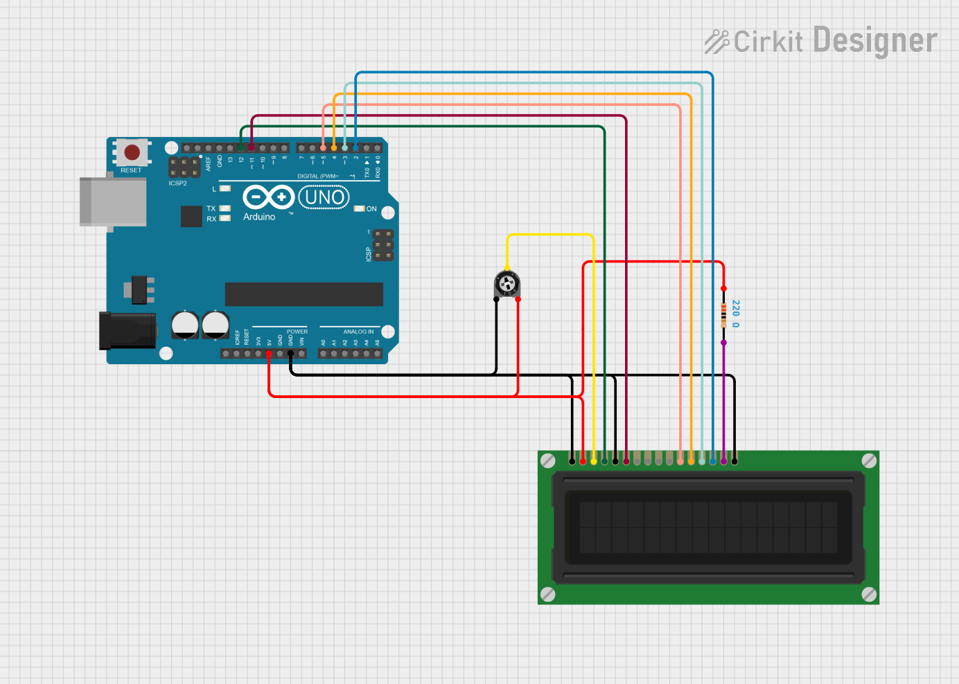
Example: Connecting to an Arduino UNO
Below is an example of how to connect and program the LCD display in 4-bit mode with an Arduino UNO:
Circuit Connections
- VSS: Connect to GND
- VDD: Connect to 5V
- V0: Connect to the middle pin of a 10kΩ potentiometer
- RS: Connect to Arduino pin 12
- RW: Connect to GND
- E: Connect to Arduino pin 11
- D4 to D7: Connect to Arduino pins 5, 4, 3, and 2 respectively
- LED+: Connect to 5V through a 220Ω resistor
- LED-: Connect to GND
Arduino Code
#include <LiquidCrystal.h>

// Initialize the library with the numbers of the interface pins
// RS = 12, E = 11, D4 = 5, D5 = 4, D6 = 3, D7 = 2
LiquidCrystal lcd(12, 11, 5, 4, 3, 2);

void setup() {
  // Set up the LCD's number of columns and rows
  lcd.begin(16, 2);

  // Print a message to the LCD
  lcd.print("Hello, World!");
}

void loop() {
  // Move the cursor to the second row, first column
  lcd.setCursor(0, 1);

  // Print a dynamic message
  lcd.print("Count: ");
  lcd.print(millis() / 1000); // Display elapsed time in seconds
}
Troubleshooting and FAQs
Common Issues and Solutions
No Display on the Screen
- Ensure the power supply (VDD) and ground (VSS) connections are correct.
- Adjust the contrast using the potentiometer connected to pin 3 (V0).
- Verify that the backlight pins (LED+ and LED-) are properly connected.
Random Characters or No Response
- Check the connections of the control and data pins to the microcontroller.
- Ensure the correct mode (4-bit or 8-bit) is configured in your code.
- Verify that the
lcd.begin()function matches the display's dimensions (16x2).
Backlight Not Working
- Confirm that a current-limiting resistor is used for the backlight.
- Check the polarity of the backlight connections (LED+ and LED-).
FAQs
Q: Can I use the LCD display with a 3.3V microcontroller?
A: Yes, but you will need a level shifter or voltage divider for the control and data pins. Additionally, the backlight may not function optimally at 3.3V.
Q: How do I display custom characters?
A: Use the createChar() function in the LiquidCrystal library to define and display custom characters.
Q: Can I use the LCD without a potentiometer for contrast adjustment?
A: Yes, you can use a fixed resistor (e.g., 1kΩ to 10kΩ) between V0 and ground, but a potentiometer provides better control.